Formula details
Product Details
Overview
What Is a Double-Chamber Vacuum Furnace?
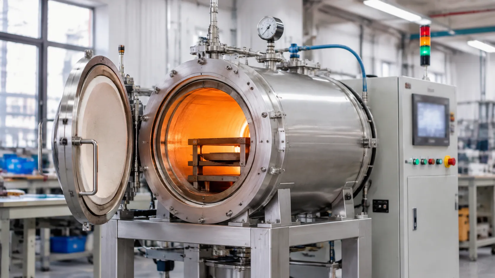
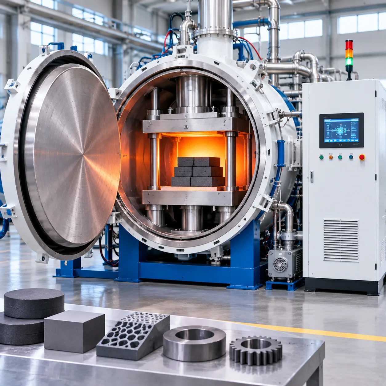
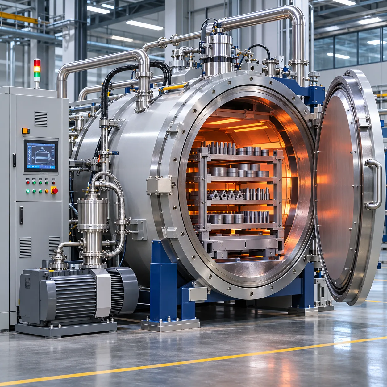
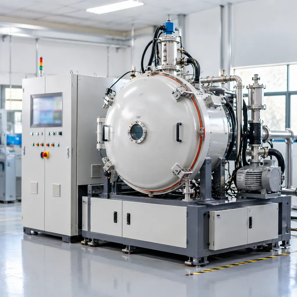
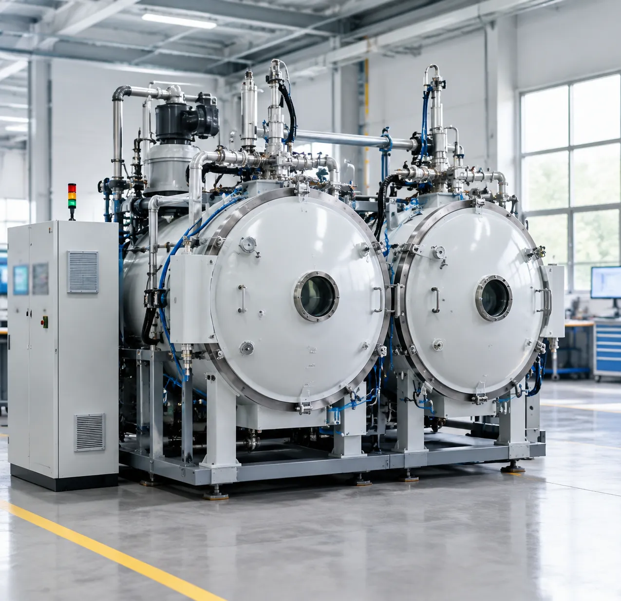
A double-chamber vacuum furnace is an advanced industrial vacuum heat treatment system engineered with two functionally isolated compartments: a dedicated heating chamber (hot zone) and an independent quenching or cooling chamber.
Unlike traditional single-chamber units that force the hot zone to heat up and cool down during every batch, our dual-chamber design decouples thermal soaking from the cooling cycle. This architecture maximizes uptime, slashes energy waste, and protects critical heating elements from thermal shock.
Heating Chamber
Continuous Hot Zone
↓
Vacuum Isolation Gate
↔ Rapid Workpiece Transfer
↓
Quench / Load Chamber
Oil Bath / Gas Quenching
Core Working Principles of Dual-Chamber Thermal Processing
The core operating logic centers on thermal isolation and parallel processing:
-
- Continuous Thermal Preservation: The heating chamber remains at operating temperature under vacuum, eliminating the cycle time lost to reheating empty furnace structures.
- Independent Atmospheric Control: The quench chamber handles high-pressure gas cooling or vacuum oil quenching without contaminating the hot zone environment.
- Seamless Batch Overlap: As one batch quenches, the heating chamber is instantly ready to accept or pre-heat the next payload.
How the Heating and Quench Chambers Interact
The two chambers function in an integrated sequence to deliver high throughput and pristine surface quality:
| Phase | Heating Chamber Role | Quench Chamber Role |
|---|---|---|
| 1. Loading & Pump-Down | Maintains base temperature under vacuum | Loads batch, seals outer door, pumps down to vacuum |
| 2. Heating & Soaking | Workpiece transfers in; performs heating, carburizing, or brazing | Remains isolated and readies quench media (oil or gas) |
| 3. Rapid Transfer | Vacuum gate opens; workpiece exits hot zone | Receives hot load immediately under controlled atmosphere |
| 4. Quench & Reset | Valve closes; hot zone stays hot, ready for next batch | Rapid oil agitation or high-pressure gas quench initiates |
Separation Valve and Rapid Transfer Mechanism Design
The engineering heart of any high-performance dual-chamber vacuum furnace lies in two critical sub-assemblies:
-
- Intermediate Vacuum Isolation Valve: A heavy-duty, water-cooled vacuum gate valve seals the boundary between both chambers. It prevents oil vapors, quench gases, and thermal radiation from degrading the heating elements or vacuum levels in the hot zone.
- High-Speed Workpiece Transfer Mechanism: Built with pneumatic cylinders, roller drives, or heavy-duty telescopic push-pull chains. This automated system transfers the payload from the hot zone to the quench station in under 15 to 25 seconds, preventing premature surface cooling and ensuring consistent martensitic transformation during critical hardening cycles.
Types of Double-Chamber Vacuum Furnaces
Double-Chamber Vacuum Oil Quenching Furnace
A vacuum oil quenching furnace is the standard choice for alloy steels, bearing steels, and heavy structural components requiring rapid cooling rates to achieve full core hardness.
Sealed oil bath: Located directly beneath or adjacent to the cooling chamber to eliminate vapor backstreaming into the hot zone.
Variable-speed agitation: Directional oil impellers ensure uniform heat extraction and minimal part distortion.
Clean surface finish: Workpieces transfer under vacuum or inert gas, exiting the oil clean and ready for tempering.
Double-Chamber High-Pressure Gas Quenching Furnace
For tool steels, dies, and high-alloy parts sensitive to thermal shock, a high-pressure gas quench furnace delivers precise cooling control without liquid quenchants.
Gas pressure range: Typically operates from 2 bar up to a 25 bar vacuum furnace configuration.
Controlled cooling: 360-degree radial nozzles direct high-velocity nitrogen or argon across the workload for uniform hardness.
Zero oil residue: Eliminates the post-wash washing cycle, cutting downstream processing time.
Dual-Chamber Vacuum Brazing and Sintering Furnaces
A two-chamber vacuum sintering and vacuum brazing furnace design isolates high-temperature joint processing or powder consolidation from the cooling stage.
Dedicated cooling section: Accelerates batch turnaround without exposing delicate heating elements to thermal cycling.
Atmosphere purity: Keeps the hot zone under ultra-clean vacuum levels, preventing joint contamination on aerospace and medical assemblies.
Process stability: Ideal for continuous production runs where thermal stability is critical across successive loads.
Combination Gas and Oil Multi-Purpose Systems
When production involves mixed alloys, we combine both liquid and gas quenching capabilities into a single dual-chamber vacuum furnace.
| Configuration | Primary Quench Medium | Typical Materials | Key Benefit |
|---|---|---|---|
| Oil Quench | Quench Oil | Carbon steel, low-alloy steel | Maximum hardenability on thick sections |
| Gas Quench | Nitrogen / Argon (up to 20+ bar) | Tool steels (H13, D2), superalloys | Low distortion, dry parts |
| Dual Quench | Oil + Pressurized Gas | Mixed production batches | Maximum operational versatility |
Understanding how these layouts fit your shop volume helps when evaluating single vs double vs triple chamber vacuum furnaces for long-term production growth.
Key Engineering Features and Components
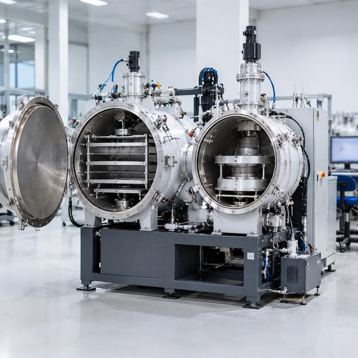
We engineer every double-chamber vacuum furnace around four foundational subsystems. These components directly dictate cycle efficiency, vacuum purity, thermal uniformity, and process repeatability.
Hot Zone Configuration: Graphite vs. All-Metal Shields
The choice of thermal insulation determines operating temperature limits, maintenance frequency, and process cleanliness. We match the hot zone design to your metallurgical requirements:
| Feature | Graphite Hot Zone | All-Metal Molybdenum Hot Zone |
|---|---|---|
| Heating Elements | Curved graphite tubes or CFC panels | Molybdenum or tungsten strip elements |
| Insulation | High-purity rigid graphite felt | Multiple molybdenum and stainless steel radiation shields |
| Max Temperature | Up to 1350°C (standard) / 2000°C (custom) | Up to 1350°C / 1600°C |
| Best Suited For | Tool steel hardening, general heat treatment | Superalloys, medical devices, clean vacuum brazing |
| Key Advantage | High thermal efficiency, lower operational cost | Ultra-clean environment with zero carbon contamination |
High-Speed Automatic Workpiece Transfer Mechanism
Workpiece transfer speed is critical for hardening processes that demand rapid quenching to prevent premature phase transformation.
-
- Pneumatic and Mechanical Drives: We use reinforced chain drives or pneumatic push-pull transfer rods sealed by dynamic vacuum feedthroughs.
- Rapid Transfer Speeds: The transfer mechanism moves loads from the heating chamber into the quench tank or cooling zone in under 10 to 15 seconds.
- Precision Positioning: Heavy-duty guide rails with optical sensors ensure the workload locks securely onto the quench elevator without jamming.
Multi-Stage Vacuum Pumping Systems
Achieving and maintaining deep vacuum levels requires a synchronized, multi-stage pumping skid tailored to your target vacuum range:
-
- Roughing & Backing Pumps: Heavy-duty rotary vane or dry screw pumps evacuate atmospheric air down to intermediate levels.
- Roots Booster Pumps: Mechanical booster blowers accelerate pump-down times during intermediate pressure transitions.
- High-Vacuum Pumps: Industrial oil diffusion pumps or high-speed turbomolecular pumps pull the system down to operating pressures of $10^{-3}$ Pa to $10^{-5}$ Pa for ultra-clean processing.
Microprocessor-Controlled PLC Automation and Recipe Management
Our double-chamber systems run on fully integrated industrial PLCs paired with high-resolution touchscreen HMIs.
-
- One-Touch Recipe Execution: Store hundreds of automated thermal profiles, precisely tracking ramp rates, soak times, partial pressure gas flows, and quench triggers according to established vacuum furnace brazing cycle guide and process parameters.
- Real-Time Data Acquisition: Continuous datalogging tracks vacuum levels, multi-point hot zone temperatures, quench oil flow, and chamber differential pressure for full quality compliance.
- Integrated Safety Interlocks: Hardware and software interlocks prevent door actuation, gas injection, or transfer cycles unless safe pressure and temperature thresholds are met.
Primary Industrial Applications for the Double-Chamber Vacuum Furnace
We build each double-chamber vacuum furnace to handle demanding thermal processes across high-precision manufacturing sectors. By separating the hot zone from the quenching area, our systems consistently deliver clean surfaces, repeatable metallurgical structures, and zero surface oxidation. Explore the broader range of vacuum furnace applications across modern manufacturing to see how thermal processing drives component durability.
Aerospace and Aviation Components
Aerospace components demand strict microstructural integrity and zero contamination. Our dual-chamber systems process critical flight hardware under deep vacuum levels:
Turbine blades and structural discs: Homogeneous solution treating and aging for nickel- and cobalt-based superalloys.
Titanium flight hardware: High-integrity processing, including specialized vacuum furnace brazing for titanium assemblies, preventing hydrogen embrittlement and maintaining high tensile strength.
Landing gear assemblies: Fast transfer to high-pressure gas quench to lock in core mechanical properties without atmospheric contamination.
Automotive Transmission and Powertrain Parts
High-throughput automotive production requires rapid cycle turnarounds and precise case hardening:
Transmission gears and pinions: Low-pressure vacuum carburizing (LPC) followed by high-speed oil or gas quenching ensures extreme case hardness with minimal distortion.
Precision drive shafts: Rapid transfer preserves uniform grain structures, eliminating post-quench straightening operations.
Fuel injection components: Clean processing keeps micro-orifices free of scaling and residue.
Tool and Die Steel Heat Treatment
Our dual-chamber vacuum heat treatment equipment delivers repeatable hardness curves for wear-resistant tooling:
Hot-work tool steels (H11, H13): High-velocity gas quenching prevents grain boundary carbide precipitation.
Cold-work die steels (D2, O1): Precise cooling-rate management stabilizes dimensions on complex stamping dies.
High-speed steels (M2, M42): Rapid cycle times reduce decarburization risk and preserve sharp cutting edges on broaches, drills, and milling inserts.
Medical Devices and Precision Brazing
Medical implants and instrumentation require pristine surfaces straight out of the quench chamber:
Orthopedic implants: Sintering and diffusion bonding of porous titanium and cobalt-chromium hip and knee joints.
Surgical cutting tools: Hardening 400-series stainless steels while preserving a bright, passive surface finish.
Clean vacuum brazing: Flux-free joining of dissimilar metals for surgical sensors, endoscopic devices, and heat exchangers without chemical post-cleaning.
Key Benefits of Double-Chamber Systems
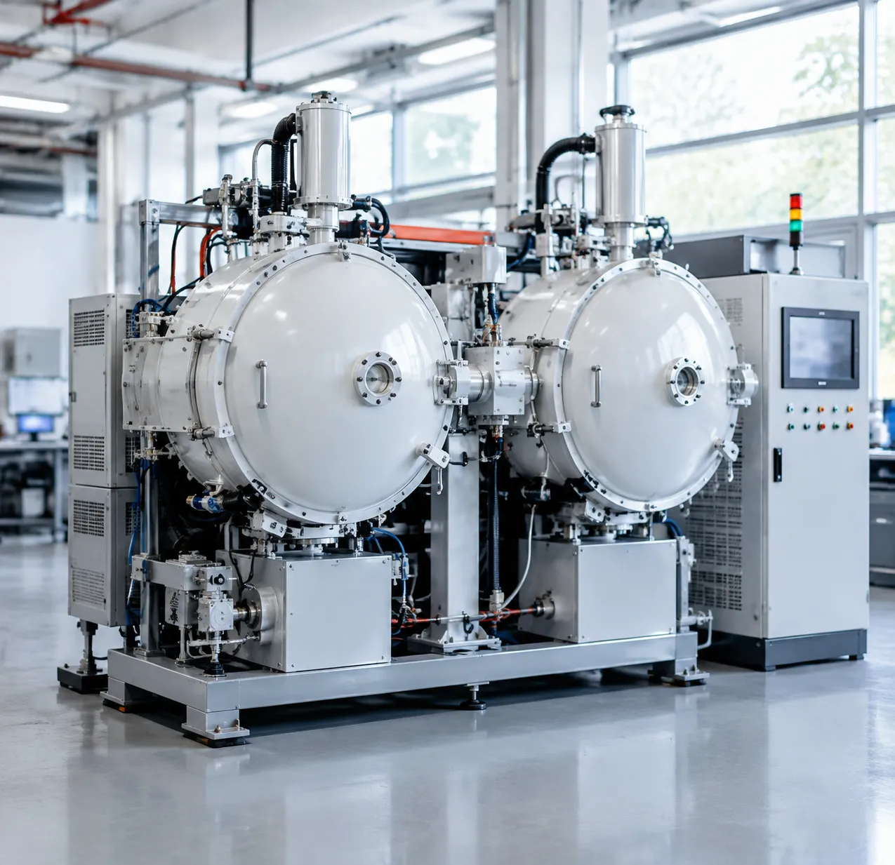
Shorter Cycle Times and Higher Production Throughput
In standard heat treatment setups, production stops while the hot zone cools down before the next load goes in. With a dual-chamber architecture, that downtime disappears:
-
- Continuous Hot Zone Operation: The heating chamber stays at working temperature while the workload moves to the quench section.
- Immediate Reloading: We can charge the next batch into the heating zone as soon as the previous load transfers to the cooling chamber.
- Maximized Output: This continuous workflow cuts overall heat treating cycle time by 30% to 50% compared to single-chamber units.
Reduced Energy Consumption by Keeping the Heating Chamber Hot
Thermal cycling wastes massive amounts of power. Keeping the hot zone continuously heated yields immediate financial and operational advantages:
-
- Zero Reheating Waste: You avoid using peak electrical loads to reheat massive insulation and heating elements from ambient temperatures.
- Extended Hot Zone Lifespan: Eliminating constant thermal shock prevents graphite and molybdenum element fatigue, cutting maintenance shutdowns.
- Lower Utility Cost per Part: Running continuous batches drives power efficiency down to optimal levels per kilogram of processed steel.
| Performance Metric | Single-Chamber Units | Double-Chamber Vacuum Furnace |
|---|---|---|
| Hot Zone Reheating | Required every cycle | Maintained continuously at temp |
| Batch Turnaround | Long cooldown delay | Immediate reload capability |
| Surface Finish | Risk of contamination | Clean, zero oxidation/decarb |
| Energy Efficiency | High thermal losses | Up to 40% less power per batch |
Superior Surface Brightness with Zero Oxidation or Decarburization
Maintaining strict vacuum integrity during high-temperature runs protects critical alloy surfaces. Workpieces exit the chamber ready for final assembly without secondary pickling, blasting, or grinding:
-
- Pristine Part Surfaces: Complete atmospheric isolation ensures parts emerge bright and clean without scale.
- Zero Decarburization: Protecting the outer steel matrix preserves surface hardness specifications directly off the quench line.
- Clean Metallurgy: When performing high-spec processing, understanding vacuum brazing vs furnace brazing key differences proves why precise vacuum separation is essential for clean joint integrity and flawless cosmetic finishes.
Precise Distortion Control and Uniform Metallurgical Properties
Controlled thermal transfers and engineered quench flow paths prevent workpiece warping and uneven core transformations:
-
- Uniform Cooling Distribution: Balanced gas nozzles or agitated oil baths deliver identical cooling rates across dense part racks.
- Repeatable Core Hardness: Predictable heat extraction ensures deep hardening on complex gears, dies, and shafts without soft spots.
- Minimal Geometric Distortion: Controlled part transfer keeps tight-tolerance components within blueprint limits, drastically reducing post-heat-treat machining costs.
Double-Chamber vs. Single-Chamber Vacuum Furnaces
Choosing between a single-chamber setup and a double-chamber vacuum furnace comes down to balancing upfront capital against operational speed and long-term production volume. While single-chamber units handle batch jobs well, our dual-chamber systems separate heating and quenching to eliminate production bottlenecks.
| Performance Metric | Single-Chamber Vacuum Furnace | Double-Chamber Vacuum Furnace |
|---|---|---|
| Cycle Time | 4 to 8 hours per load | 1.5 to 3 hours per load |
| Hot Zone Thermal Shock | High (heats & cools every cycle) | Minimal (stays at operating temp) |
| Heating Element Lifespan | Moderate (frequent thermal stress) | Extended (stable temperature state) |
| Quench Capabilities | Gas quenching only | Oil quench, high-pressure gas, or both |
| Energy Consumption | High per part (repeated heating) | Up to 35% lower per processed part |
| Initial Capital Cost | Lower base investment | Higher upfront investment |
Cycle Time and Batch Turnaround
In a single-chamber unit, the entire vessel must ramp up to temperature, hold, and cool down before unloading. With a dual-chamber vacuum furnace, the heating zone stays continuously hot under vacuum.
-
- The load transfers into the quench chamber in seconds.
- You can load the next batch into the hot zone immediately while the previous load cools.
- Overall heat treating cycle time drops by 40% to 60%, doubling your daily batch turnaround.
Thermal Efficiency and Hot Zone Lifespan
Repeatedly heating and cooling a hot zone creates severe thermal fatigue on heating elements, insulation, and ceramic supports. Keeping the hot zone at temperature in a two-chamber layout delivers two distinct benefits:
-
- Lower power draw: You avoid wasting electrical power reheating furnace insulation from ambient temperatures for every batch.
- Longer element life: Heating elements and graphite or metallic insulation shields suffer far less thermal shock, slashing maintenance downtime and replacement costs.
Quenching Flexibility and Cooling Speeds
Single-chamber furnaces are generally limited to gas cooling to avoid contaminating the heating chamber with oil vapors. Our dual-chamber designs offer complete quenching flexibility across diverse metallurgical specs:
-
- Vacuum oil quenching: Achieve ultra-fast cooling rates for heavy cross-section alloy steels without oil vapor migrating into the hot zone.
- High-pressure gas quench: Use gas quench pressures up to 20 bar or higher for clean, controlled hardening.
- Integrated processing: Easily switch recipes across standard vacuum heat treatment furnace cycles and critical quenching jobs on the same production line.
Capital Costs vs. Operating ROI
A single-chamber unit requires a smaller upfront budget, making it suitable for low-volume toolrooms or variable R&D work. However, when evaluating high-volume industrial production, our double-chamber systems yield a far higher return on investment (ROI).
The combined savings from reduced power consumption, extended hot zone lifespans, and double the output per shift offset the initial equipment cost within the first 12 to 18 months of continuous operation. Explore our broader lineup of industrial vacuum furnaces to match the exact capacity and configuration your shop floor demands.
How to Choose the Right Double-Chamber Vacuum Furnace
Selecting the right double-chamber vacuum furnace comes down to matching your production volume, alloy requirements, and operating budget with the correct hardware configuration. We prioritize real shop-floor performance metrics over generic spec sheets to ensure reliable throughput.
Determining Hot Zone Dimensions and Batch Weight Capacity
We always size the heating chamber based on your largest workpiece envelope plus the necessary fixturing clearances.
-
- Usable Dimensions: Calculate the width, height, and length of your densest part basket, leaving at least 50 mm to 75 mm clearance from heating elements to prevent localized overheating.
- Gross Weight Rating: Always factor in the weight of the charging baskets, grids, and fixtures alongside the payload. Under-sizing the load mechanism leads to transfer carriage binding and premature drive failure.
Matching Temperature and Ultimate Vacuum Levels
Your thermal process determines both the heating element package and the required vacuum pumping speed:
-
- Operating Temperatures: Standard tool steel hardening requires up to 1300°C (2372°F). High-temperature brazing or sintering cycles often demand ratings up to 1400°C or higher.
- Vacuum Levels: Standard mechanical and Roots pump packages achieve rough vacuum levels ($10^{-1}$ to $10^{-2}$ mbar) for standard hardening. For titanium, superalloys, or critical brazing, we integrate diffusion or turbomolecular pumps to reach high vacuum ranges ($10^{-4}$ to $10^{-5}$ mbar).
Selecting Oil, Gas, or Dual Quench Capabilities
The quenching method directly dictates metallurgical hardness, part cleanliness, and distortion control:
-
- Vacuum Oil Quenching: Best for heavy cross-section carburized parts, low-alloy steels, and high-volume automotive gears requiring rapid critical cooling rates.
- High-Pressure Gas Quenching: Ideal for high-alloy tool steels, die blocks, and aerospace parts. Choosing the correct vacuum gas quenching pressure—from 2 bar up to high-velocity systems like a 25 bar gas quench vacuum furnace—ensures core hardness without the need for post-wash operations.
- Combination Dual Systems: Recommended for commercial heat treaters handling diverse alloy mixes needing both oil and pressurized gas options in one unit.
Double-Chamber Selection Matrix
| Selection Factor | Standard Hardening & Tooling | Aerospace & Clean Brazing | Heavy-Duty Carburizing |
|---|---|---|---|
| Hot Zone Material | Graphite felt & elements | All-metal molybdenum shields | Graphite with reinforced hearth |
| Pumping System | Rotary vane + Roots blower | Rotary vane + Roots + Diffusion | Mechanical pump + Roots blower |
| Quench Medium | High-pressure gas (6–16 bar) | Inert gas (2–6 bar) | Fast-quench vacuum oil |
| Ultimate Vacuum | 1 × 10⁻² mbar | 5 × 10⁻⁵ mbar | 5 × 10⁻² mbar |
Evaluating Maintenance, Spare Parts, and Power Draw
-
- Transfer Mechanism Reliability: Look for externally driven transfer systems with accessible seals so you can service drive motors and pneumatic cylinders without entering the chamber.
- Isolation Valve Maintenance: Ensure the intermediate vacuum separation gate valve allows quick O-ring replacement and seal cleaning during routine shutdowns.
- Connected Electrical Load: Compare power consumption during holding cycles. Double-chamber designs eliminate the energy spikes of repeated hot zone reheat cycles, delivering up to 30% lower kilowatt-hour usage per processed ton.
Frequently Asked Questions About Double-Chamber Vacuum Furnaces
How fast is the transfer time from the heating to the quench chamber?
In our double-chamber vacuum furnace designs, the internal pneumatic or mechanical loader transfers the workload from the heating chamber to the quench chamber in under 15 seconds, with high-speed configurations achieving transfers in as fast as 7 to 10 seconds. Minimizing this transfer window prevents surface cooling, eliminates pre-transformation phases, and ensures consistent hardness across deep-hardening alloy steels.
Can a double-chamber furnace run both oil and gas quench in the same unit?
Yes. We engineer combination systems where the front quench chamber houses both an agitated oil bath and a high-pressure gas cooling system (up to 20 bar). This gives you the flexibility to process heavy cross-section carburized gears in vacuum oil and switch directly to high-pressure gas quenching for delicate tool steels (like H13 or D2) without changing furnaces or reconfiguring lines.
+---------------------+-------------------------------+----------------------------------+
| Quench Type | Typical Cooling Medium | Best Suited For |
+---------------------+-------------------------------+----------------------------------+
| Vacuum Oil Quench | Low-vapor-pressure quench oil | Heavy gears, plain carbon steels |
| High-Pressure Gas | Nitrogen / Argon (2 to 20 bar)| Tool steels, superalloys, dies |
| Multi-Purpose Unit | Oil bath + Top gas nozzles | Mixed-production job shops |
+---------------------+-------------------------------+----------------------------------+
How does keeping the hot zone continuously heated save electricity?
In a single-chamber unit, the entire hot zone—including molybdenum shields, graphite insulation, and heating elements—is repeatedly cooled during quenching and reheated for the next batch. In our dual-chamber layout, the heating chamber stays at soaking temperature under vacuum while the previous load cools in the adjacent chamber.
By eliminating the need to ramp thermal mass from ambient on every batch, continuous-heat operation reduces net energy consumption by 30% to 45% per kilogram of processed steel. To ensure this thermal cycling remains efficient over long production runs, regular vacuum furnace calibration keeps heating elements and sensor offsets performing within tight tolerances.
What maintenance does the vacuum separation door require to prevent leaks?
The intermediate vacuum valve maintains the critical seal between the hot zone and the quench tank. Key maintenance steps include:
Elastomer O-Ring Inspection: Clean and lubricate fluorocarbon (Viton) seals weekly; replace them every 6 to 12 months.
Thermal Deflector Cleaning: Remove vaporized oil residue, soot, and condensed process deposits from the door shield surfaces monthly.
Pneumatic Cylinder Check: Inspect guide rods and pneumatic cylinder seals for smooth actuation and correct mechanical clamping pressure.
Helium Leak Detection: Run quarterly vacuum integrity tests across the door flange to guarantee baseline leak-back rates remain below 1 × 10⁻³ mbar·L/s.
How clean are the workpieces after vacuum oil quenching?
Parts exit the double-chamber vacuum furnace free of scale, oxidation, and decarburization because the oil immersion takes place in an oxygen-free, partial-pressure nitrogen environment. Understanding the principles of heat transfer in a vacuum furnace helps explain why the controlled atmosphere protects part geometry while preventing surface chemistry alterations. Although a light film of quench oil remains on the parts, it washes off easily in a standard alkaline or ultrasonic wash system, leaving a bright, uniform metallic finish ready for downstream tempering or machining.