Formula details
Product Details
Overview
Carbide Vacuum Sintering Furnace Working Principles and Metallurgy
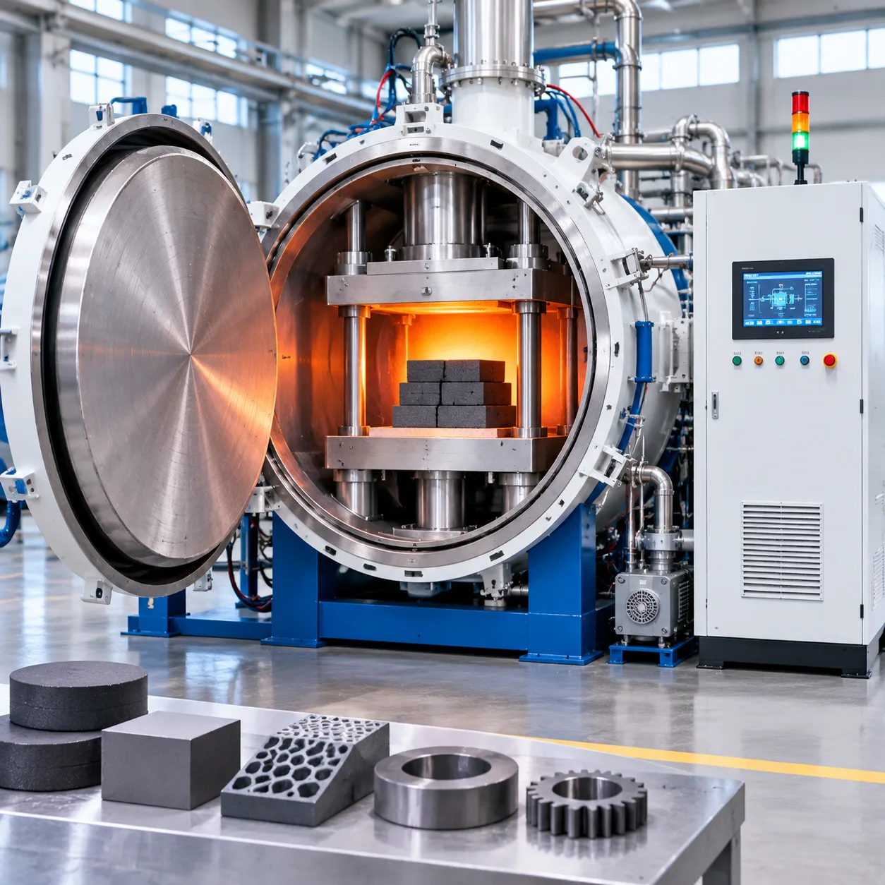
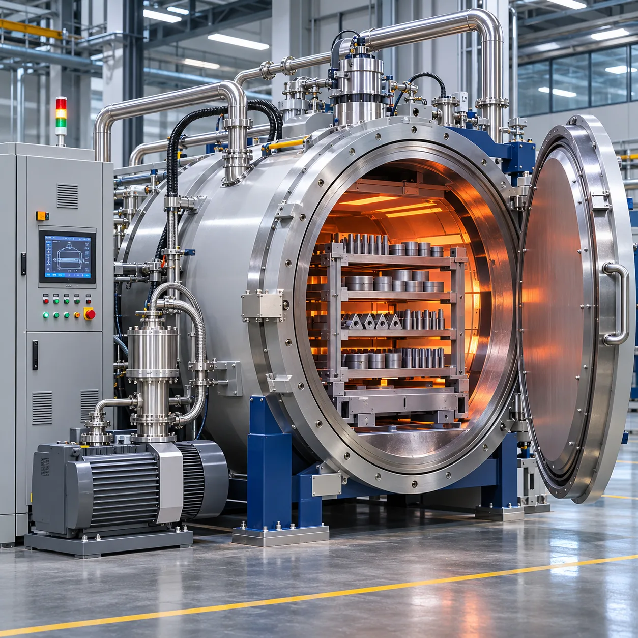
Sintering premium cemented carbides demands uncompromising atmosphere control and thermal precision. In our carbide vacuum sintering furnace systems, we design the entire thermal cycle around the complex phase transformations of tungsten carbide (WC-Co), titanium carbide (TiC), and titanium carbonitride (TiCN) cermets. Achieving theoretical density requires eliminating voids before the liquid phase emerges, ensuring complete structural integrity across every batch.
Critical Metallurgy of WC-Co, TiC, and Cermet Consolidation
Consolidating powder compacts into dense, defect-free tooling hinges on precise carbon control and phase stabilization:
-
- Carbon Balance Management: Preventing the formation of brittle eta-phase (Co_3W_3C or Co_6W_6C) caused by decarburization, while avoiding free carbon precipitation that undermines transverse rupture strength (TRS).
- Wetting and Capillary Action: Ensuring molten cobalt uniformly coats carbide grains at the eutectic point (approx. 1,320°C to 1,380°C).
- Grain Growth Inhibition: Controlling dwell times and temperatures to halt abnormal WC grain coarsening when working with submicron and ultrafine grain formulations.
Eliminating Micro-Porosity and Cobalt Pooling
Non-uniform heating or improper gas evacuation leads directly to cobalt pooling and internal micro-porosity (A, B, and C-type porosity according to ISO 4505 standards). We resolve this by synchronizing dynamic ramp rates with precise gas transitions:
-
- Ramp Stabilization: Slow, calculated heating between 800°C and 1,150°C allows interstitial gases to escape before pore closure.
- Uniform Capillary Flow: Symmetrical heating prevents localized temperature spikes that draw liquid cobalt to the surface, eliminating surface pooling and core starvation.
Integrated Thermal Debinding and Dewaxing
Residual forming binders—whether paraffin wax or polyethyleneglycol (PEG)—must be completely extracted without leaving cracked compacts or residual carbon soot.
-
- Negative Pressure Sweep: We execute debinding under low vacuum (10 mbar to 300 mbar) using high-purity argon or hydrogen sweep gas.
- Direct Evaporation Pathway: The carrier gas sweeps volatile organic compounds directly into our dual-stage condensing traps, preventing pump contamination and element deposition.
High-Vacuum Solid-State Sintering Phase
Before reaching the liquidus line, the furnace switches to a high-vacuum state ($10^{-2}$ to $10^{-4}$ mbar):
-
- Oxide Reduction: Surface oxides on WC and cobalt particles decompose and pump away, exposing bare metal contacts.
- Interparticle Necking: Solid-state diffusion drives initial shrinkage, densifying the body up to 90–95% of theoretical density prior to liquid formation.
Partial-Pressure Sintering to Suppress Cobalt Evaporation
Cobalt has a high vapor pressure at peak sintering temperatures (1,400°C to 1,500°C). Running deep vacuum during the liquid phase volatilizes cobalt, depleting surface binder content and ruining wear resistance.
-
- Controlled Backfill: Our automated system introduces an inert gas blanket (typically Ar) at 10 to 50 mbar during peak hold times.
- Vapor Pressure Suppression: This controlled partial pressure suppresses the mean free path of cobalt vapors, keeping the cobalt binder uniformly locked within the grain matrix.
Forced Inert Gas Cooling
Cycle turnaround times directly dictate plant profitability. Once solid-state transformation completes below the eutectic point, our furnaces initiate rapid, high-pressure gas quenching:
-
- Dual Cooling Media: Automated directional nozzles introduce high-purity argon (Ar) or nitrogen (N2).
- Grain Structure Freezing: Controlled rapid cooling arrests the cobalt binder phase, refining grain boundary distribution and slashing total cycle duration by up to 40% without thermal shock or micro-cracking.
Carbide Vacuum Sintering Furnace Chamber and Hot Zone Architecture
Double-Walled Vessel Engineering and Vacuum Sealing
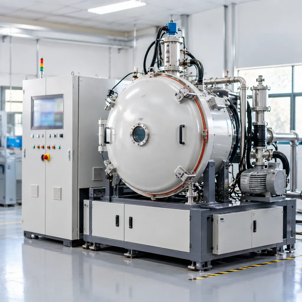
The main vessel serves as the structural foundation of the furnace, handling both deep vacuum conditions and pressurized cooling routines.
-
- Double-Walled Stainless Steel Construction: We fabricate the inner and outer shells from heavy-gauge 304 or 316L stainless steel. Full-coverage water jackets with integrated internal baffles eliminate localized thermal hotspots, prevent shell warping, and protect operators during runs up to 1600°C.
- Precision O-Ring Grooves: Flange surfaces are precision-machined with smooth dovetail or trapezoidal seal tracks that prevent gasket displacement during vacuum-to-overpressure transitions.
- Fluororubber (FKM/Viton) Seals: We fit dual-track FKM seals engineered to resist hardening and mechanical degradation caused by thermal cycling, radiative heat, and binder volatiles.
Graphite Hot Zone Architecture and Load Support
Consistent metallurgy across tight batches of tungsten carbide inserts and wear parts requires absolute temperature uniformity. Much like the thermal uniformity principles highlighted in our vacuum brazing furnace temperature guide and settings, our hot zone architecture ensures strict control across every shelf.
-
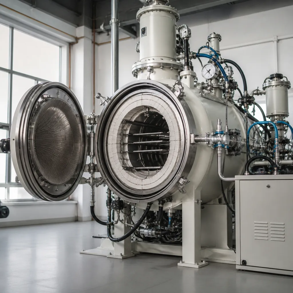
- 360-Degree Radial Heating Elements: We utilize high-purity isostatic graphite heating elements arrayed in a circular pattern around the charge. This 360-degree coverage guarantees uniform heat flux and eliminates cold zones during solid-state and liquid-phase sintering.
- Rigid Carbon Felt and CFC Shielding: The insulation pack features rigid, low-density carbon felt backed by carbon-fiber-reinforced carbon (CFC) protective skins. This construction minimizes gas retention, accelerates vacuum pump-down, and prevents mechanical erosion during high-velocity gas cooling.
- Heavy-Duty Hearth Supports: To support dense trays loaded with carbide mining bits or large cold-heading dies, our hearth rests on reinforced graphite support pillars tied directly into the external vessel frame. This layout prevents sagging, shifting, and thermal creep at peak sintering temperatures.
Binder Extraction and Sweep Gas Flow Paths
Handling paraffin, PEG (polyethylene glycol), or specialized organic binders requires isolating volatile hydrocarbons before they can foul the hot zone or destroy the vacuum pumping system. Our vacuum dewaxing sintering furnace setup isolates these vapors at the source.
-
- Dedicated Sweep Gas Routing: An internal graphite muffle directs inert sweep gas (argon or hydrogen) directly across the work charge. The controlled gas stream sweeps evaporated VOCs straight into the exhaust path, shielding heating elements and insulation from carbon buildup and soot contamination.
- Dual-Stage Condensation Trap: Vapors enter a high-efficiency condensing system where multistage chilled plates solidify paraffin and PEG volatiles out of the stream before the gas reaches the vacuum booster pumps.
- Automated Drain and Quick-Clean Ports: Melted binder collects in a heated, isolated reservoir equipped with an automated drain valve. Tool-less quick-release access ports let maintenance crews inspect and clean condensing baffles in minutes rather than halting production for hours.
Multi-Stage Vacuum Pumping and Atmosphere Dosing Systems
Precise atmosphere and pressure control dictate metallurgical consistency in every carbide vacuum sintering furnace we build. Without stable vacuum levels and balanced gas dosing, you risk cobalt depletion, irregular carbon activity, and porosity in your finished compacts.
Rapid Pump-Down and Deep-Vacuum Pumping Skids
We engineer the vacuum system to move quickly through critical outgassing stages while keeping cycle turnaround times low:
-
- Primary Backing & Roots Configuration: Heavy-duty rotary vane or dry screw backing pumps paired with high-displacement Roots blowers handle bulk atmospheric volume rapidly, pulling the chamber down to working vacuum without pump cavitation or oil backstreaming.
- Optional Diffusion Pump Integration: For high-purity cermets and specialized grades requiring deep-vacuum processing down to $10^{-3}$ Pa, we integrate a water-cooled oil diffusion pump equipped with a cold trap to freeze out stray hydrocarbon traces.
- Contaminant Isolation: Automated pneumatic isolation valves segregate the primary pumping manifold during dewaxing phases to shield delicate vacuum stages from volatile binder residue.
Full-Range Vacuum Metrology
A single vacuum gauge cannot accurately measure the complete span from rough vacuum to high vacuum, especially with shifting gas mixtures. We install a three-tier sensor network:
| Sensor Type | Effective Range | Primary Cycle Function |
|---|---|---|
| Capacitive Diaphragm Gauge (CDG) | 0.1 mbar – 100 mbar | Direct gas-independent measurement during partial-pressure sintering |
| Pirani Gauge | 10³ mbar – 10⁻¹ mbar | Chamber roughing, dewaxing pressure monitoring, and leak-check staging |
| Penning (Cold Cathode) Gauge | 10⁻¹ mbar – 10⁻⁵ mbar | High-vacuum monitoring during solid-state and liquid-phase sintering |
Reviewing proper pressure monitoring is a core consideration when analyzing vacuum furnace applications and benefits across demanding cemented carbide sintering workflows.
Gas Dosing and Dynamic Partial-Pressure Regulation
Preventing cobalt loss at liquid-phase temperatures requires exact counter-pressure management. We handle this through closed-loop gas delivery:
-
- Precision Mass Flow Controllers (MFC): Calibrated digital MFCs supply exact volumes of high-purity argon, hydrogen ($H_2$), and methane ($CH_4$). Hydrogen aids residual oxide reduction during low-temperature ramp-up, while trace methane stabilizes the carbon potential to prevent brittle eta-phase formation.
- Active Partial-Pressure Holding: The system regulates furnace pressure smoothly between 10 mbar and 50 mbar during elevated thermal holds. A motor-driven throttle valve dynamically balances gas inlet flow against the pumping port to keep pressure steady regardless of outgassing shifts.
- Overpressure Sintering Capabilities: For specialized tooling grades, our vacuum pressure sintering furnace units support positive inert gas backfills to compact micro-voids prior to final cooling.
Industrial PLC Control, Sensing, and Failsafe Interlocks
Our automation platform puts complete recipe control directly into the hands of your process engineers while running automated hardware protections in the background.
-
- Multi-Segment Cycle Programming: The industrial PLC system stores hundreds of user-defined profiles, automatically stepping through dewaxing ramp rates, partial-pressure holds, deep-vacuum soaking, and gas quench stages.
- Dual-Spectrum Thermal Sensing: Temperature is managed across the entire thermal band using motorized retractable tungsten-rhenium (Type C) thermocouples for lower-to-mid ranges, automatically withdrawing as two-color optical pyrometers take over above 1,400°C to avoid sensor drift and sheath brittleness.
- Hardware Safety Interlocks: Instant automated trips safeguard the furnace against over-temperature conditions, pneumatic line drops, primary power disruptions, and cooling water flow or temperature anomalies, immediately locking the chamber into a safe, inert gas blanket.
Carbide Vacuum Sintering Furnace Technical Specifications
| Specification Parameter | Model CVS-336 | Model CVS-448 | Model CVS-6612 | Model CVS-8815 |
|---|---|---|---|---|
| Effective Hot Zone (W×H×L) | 300 × 300 × 600 mm | 400 × 400 × 800 mm | 600 × 600 × 1200 mm | 800 × 800 × 1500 mm |
| Max Loading Capacity | 200 kg | 500 kg | 1,200 kg | 2,500 kg |
| Ultimate Vacuum (Dry/Clean) | 5.0 × 10⁻¹ Pa | 5.0 × 10⁻¹ Pa | 5.0 × 10⁻¹ Pa | 5.0 × 10⁻¹ Pa |
| Operating Vacuum (Roughing) | 1 to 10 Pa | 1 to 10 Pa | 1 to 10 Pa | 1 to 10 Pa |
| Max Operating Temperature | 1,600°C | 1,600°C | 1,600°C | 1,600°C |
| Temperature Uniformity | ± 5 °C (at 1,450°C) | ± 5 °C (at 1,450°C) | ± 5 °C (at 1,450°C) | ± 5 °C (at 1,450°C) |
| Heating Power Rating | 65 kVA | 110 kVA | 210 kVA | 330 kVA |
| Forced Cooling Gas Pressure | le 0.2 MPa (Ar/N_2) | le 0.2 MPa (Ar/N_2) | le 0.2 MPa (Ar/N_2) | le 0.2 MPa (Ar/N_2) |
Thermal Uniformity and Power Distribution
-
- Tight Uniformity Margins: Our multi-zone graphite element design locks temperature variation within ± 5 °C across the entire working volume from 600°C up to 1,600°C, verified via 9-point thermal surveys.
- Low-Voltage High-Current Supply: Stepped-down via multi-tap transformers to minimize arcing in partial-pressure atmospheres while feeding rugged graphite heating arrays.
- Accelerated Gas Cooling: Integrated closed-circuit radial blowers with heavy-duty copper-finned heat exchangers drop the core charge from sintering temperatures down to handling levels in under 120 minutes. For operations demanding rapid hardening or extreme quenching velocities, we also integrate high-pressure engineering derived from our gas quench vacuum furnace systems.
Facility and Utility Connection Requirements
Reliable furnace operation requires stable, clean industrial inputs across three key utility channels:
-
- Electrical Supply:
- Input Voltage: 380V / 415V / 480V AC (± 10%), 3-phase, 50/60 Hz.
- Control Voltage: 24V DC auxiliary power with dedicated online UPS backup for the industrial PLC and critical fail-safe interlocks.
- Cooling Water Loop:
- Supply Pressure: 0.3 to 0.5 MPa (3.0 to 5.0 bar).
- Inlet Water Temperature: 15°C to 25°C (closed-loop system with automated dual-pump skid).
- Water Quality: Total hardness < 6 °dH (< 100 mg/L CaCO_3), pH 7.0–8.5, filtration level le 50 μm to prevent scale accumulation on jacket walls.
- Process Gases:
- Argon (Ar): Purity ge 99.999% (5N grade), inlet pressure 0.4 to 0.6 MPa, dew point le -65 °C.
- Hydrogen (H_2): Purity ge 99.999%, supplied through explosion-proof safety train with backflow arrestors at 0.2 to 0.4 MPa.
Industrial Applications for Cemented Carbides and Cermets
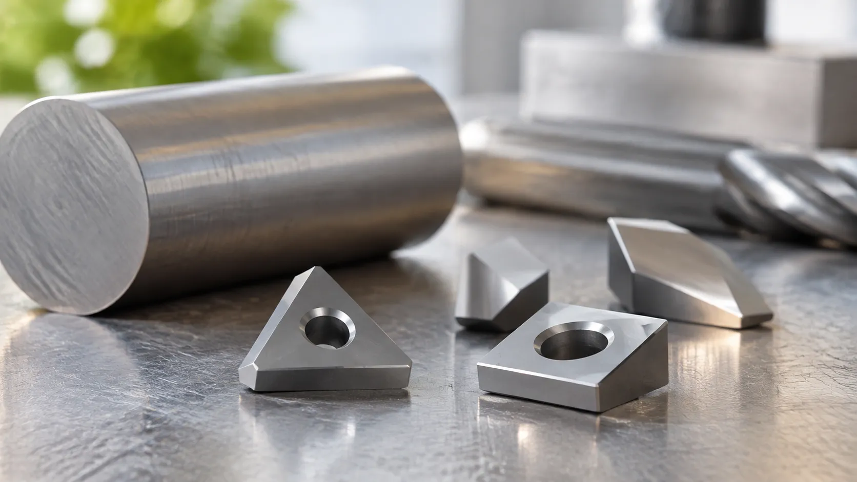
Sintering Indexable Cutting Inserts, End Mills, and Micro-Drills
Machining tools require razor-sharp cutting edges and predictable dimensional stability directly out of the hot zone.
Zero surface depletion: Precise partial-pressure control prevents cobalt evaporation on outer cutting faces, preserving substrate integrity for CVD and PVD coatings.
Uniform hardness: Consistent radial heat distribution ensures uniform binder phase distribution across micro-drills and multi-flute end mills, preventing edge chipping and premature fracture.
Flawless density: Complete binder removal during low-temperature cycles eliminates residual porosity (A02/B02 standards or better) across high-speed tooling geometries.
Processing Wear Parts, Wire Drawing Dies, and Cold Heading Tools
Forming tools face continuous shock and severe friction. Our vacuum dewaxing sintering furnace technology optimizes the consolidation of high-cobalt and medium-grain grades:
Wire drawing dies and pelleted nibs: Uniform liquid-phase sintering provides high compressive strength and prevents micro-voids under heavy drawing friction.
Cold heading punches and dies: Stable thermal cycles eliminate thermal gradients across heavy cross-sections, preventing internal tensile stresses and premature fatigue cracks.
Fluid handling wear rings and nozzles: Pore-free microstructures guarantee long service lives in high-pressure, abrasive, and corrosive pumping environments.
Consolidation of Heavy-Duty Mining Buttons and Drilling Teeth
Mining, quarrying, and road trenching demand extreme impact resistance and high fracture toughness.
Liquid-phase control: Our thermal cycles handle coarse-grained WC-Co grades without cobalt pooling, ensuring uniform binder distribution throughout large-diameter rock drill inserts.
Heavy-load processing: Reinforced hearth designs support heavy charges of down-the-hole (DTH) drill bits, tunneling cutter picks, and asphalt planers without thermal sag or uneven heat soak.
Structural uniformity: Gradual cooling sequences prevent core cracking in oversized components used for oil and gas drilling equipment and heavy powder metallurgy wear components.
Sintering TiCN Cermets and Advanced Powder Metallurgy Components
Titanium carbonitride (TiCN) cermets offer high hot hardness and chemical stability, but they are exceptionally sensitive to gas atmospheres and phase shifts during sintering.
Nitrogen partial-pressure management: Closed-loop atmosphere dosing stops nitrogen loss from the Ti(C,N) lattice, preventing brittle phase formation at elevated temperatures.
Tailored core-rim structures: Accurate multi-segment temperature ramping controls the dissolution and reprecipitation of complex carbonitrides, producing uniform hard-phase grain boundaries.
Versatility for high-performance alloys: Beyond standard cermets, the furnace easily adapts to process non-standard binders and specialized advanced materials that demand strict vacuum levels and precise sweep-gas cycles.
Carbide Vacuum Sintering Furnace Quality Standards and Factory Testing
Pressure Vessel Codes and Electrical Compliance
Structural integrity and operator safety dictate our design philosophy. We build pressure vessels and vacuum chambers under strictly audited global frameworks:
-
- ASME & PED Certification: Chambers comply with ASME Section VIII Division 1 guidelines and the European Pressure Equipment Directive (PED 2014/68/EU) for positive pressure purging and overpressure stages.
- CE & NFPA Compliance: Control cabinets are built to CE low-voltage and electromagnetic compatibility (EMC) directives, with optional NFPA 79 and UL 508A configurations for North American installations.
- Fail-Safe Interlocks: High-speed pneumatic safety dump valves, over-temperature switches, and dual cooling water circuit flow sensors operate independently of the primary PLC.
Helium Leak Detection and Vacuum Integrity
A vacuum leak during the liquid-phase sintering of cemented carbide ruins an entire production charge via cobalt oxidation. To prevent this, every carbide vacuum sintering furnace undergoes localized and overall helium mass spectrometer sniffer testing.
-
- Standard Helium Leak Rate: Tested and certified to < 0.05 Pa·L/s.
- Total Rate of Rise (RoR): Tested after an 8-hour bake-out cycle to verify an RoR under 0.5 Pa/h on an isolated, cold chamber.
- Sealing Surface Audits: Precision-machined O-ring grooves and double fluororubber seals are inspected under optical magnification prior to assembly.
Thermal Uniformity Surveys (TUS) Under AMS 2750
Temperature deviations lead to uneven cobalt distribution, abnormal grain growth, and inconsistent shrinkage across carbide components. We perform comprehensive multi-point thermal profiling conforming to AMS 2750 and CQI-9 pyrometry standards.
-
- Hot Zone Uniformity: Calibrated to within ±5°C throughout the effective working envelope up to 1,500°C.
- Thermocouple Matrix: 9-point to 15-point tungsten-rhenium thermocouple fixtures map the empty and loaded hot zone geometry.
- Digital Data Logging: Continuous automated logging verifies stability at critical dwell points, including binder boil-off and final liquid-phase sintering plateaus.
Pre-Shipment Dry Runs and Factory Acceptance Testing (FAT)
Before final teardown and crating, our engineering team executes a comprehensive, multi-cycle FAT witnessed directly by your technical team or via live remote telemetry. Much like the protocol on our 200kW vacuum sintering furnace series, every unit must successfully clear full thermal and vacuum stress testing.
| Test Phase | Operating Parameters | Acceptance Criteria |
|---|---|---|
| Deep Vacuum Ultimate Test | Roots blower + rotary backing pump | Vacuum level < 5 × 10⁻¹ Pa within 25 minutes |
| Full Thermal Soak Run | Max design rating (up to 1,600°C) | Continuous hold for 180 min without element deformation |
| Hot Zone Expansion Check | Ramp rate up to 10°C/min | Zero graphite thermal binding or hearth sagging |
| Gas Quench Turnaround | Forced inert argon circulation | Hot-to-handling cycle time strictly within validated spec |
| Dewaxing Sweep Simulation | Partial-pressure gas flow dynamics | MFC flow response stability within ±1% across all ports |
These rigorous baseline runs guarantee your furnace arrives at your production facility ready to produce high-density cemented carbide inserts, wear tools, and cermets from day one.
Turnkey Field Engineering and Plant Support Services
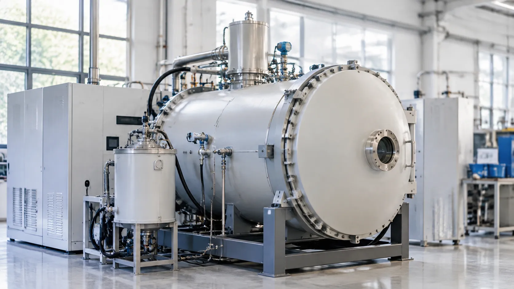
Installing a carbide vacuum sintering furnace requires more than just dropping equipment onto a shop floor. We partner directly with your engineering and production teams to handle everything from initial footprint planning to final metallurgical validation. Our field engineers ensure your sintering line hits target density, carbon balance, and production cycle times right out of the gate.
Custom Chamber Sizing and Modular Skid Configurations
Every production floor has unique physical constraints and workflow demands. Through our custom solutions and design engineering, we match furnace dimensions and layout directly to your facility.
-
- Tailored Hot Zone Dimensions: We scale the effective hot zone volume to match your specific batch weights, tray configurations, and ceiling clearances.
- Modular Vacuum Pumping Skids: Pumping systems, condensation binder traps, and gas dosing manifolds can be integrated onto a unified frame or configured as remote skids to fit tight factory layouts.
- Flexible Utility Drops: Water, power, and gas connections are engineered to tie into your plant utilities with minimal structural rework.
On-Site Assembly, Commissioning, and Metallurgical Debugging
Our technicians oversee mechanical placement, electrical hookups, and primary utility integration. Once powered, we handle complete system commissioning:
-
- Vacuum Integrity Verification: Full helium mass spectrometer leak testing across all chamber joints, feedthroughs, and valves.
- Thermal Mapping: Multi-point temperature uniformity verification under operational vacuum and partial-pressure conditions.
- Metallurgical Process Tuning: We do not walk away until test batches meet your exact metallurgical targets. Our engineers dial in debinding sweep-gas velocities, partial-pressure cobalt suppression thresholds, and cooling ramp rates to eliminate carbon porosity, cobalt pooling, and part distortion.
Operator Training and Safety Interlocks
We train your furnace operators and maintenance personnel directly on the shop floor. Training sessions prioritize practical, hands-on procedures:
-
- Recipe Programming: Creating, testing, and modifying multi-segment temperature, atmosphere, and vacuum profiles via the industrial PLC interface.
- Safety System Response: Detailed walkthroughs of automated safety interlocks, covering emergency power disruptions, loss of cooling water flow, over-temperature trips, and overpressure venting.
- Preventive Cleaning Protocols: Routine maintenance steps for cleaning binder collection traps, inspecting fluororubber door seals, and cleaning pyrometer sight glasses.
Spare Parts Logistics and Critical Consumables
Unplanned downtime ruins sintering schedules. We maintain a reliable supply chain of replacement components and wear parts engineered specifically for our graphite hot zone vacuum furnaces.
| Component | Function | Recommended Spares On Hand | Service Life Interval |
|---|---|---|---|
| Isostatic Graphite Elements | Hot zone radial heating | 1 Complete element set | 2 to 4 Years (profile dependent) |
| CFC Hearth Plates & Fixtures | Tray support and part loading | 2 Base sets | 3 to 5 Years |
| W-Re Thermocouples | High-temperature monitoring | 2 Sets (Type C) | 6 to 12 Months |
| Fluororubber O-Rings | Main door and flange vacuum seals | 2 Complete seal kits | 12 Months |
| Condenser Gaskets & Traps | Paraffin / PEG extraction zones | 4 Gasket sets | 6 Months |
Remote Diagnostics and Continuous Engineering Support
Every carbide vacuum sintering furnace includes secure remote network connectivity for ongoing plant support. With your permission, our controls engineers can access the PLC system to:
-
- Diagnose system alarms, valve timing delays, and sensor faults in real time.
- Analyze historical run logs to identify vacuum pump performance decay or heating element degradation.
- Push software updates and optimize heating curves without waiting for a field service visit.
Carbide Vacuum Sintering Furnace Technical FAQs
How We Prevent Cobalt Evaporation at High Temperatures
Cobalt has a high vapor pressure once your charge passes 1350°C. If you pull a deep vacuum at peak sintering temperatures (1400°C–1500°C), the cobalt flashes off, causing surface depletion, bad skin hardness, and cobalt pooling.
To solve this, our systems automatically switch from fine vacuum to a controlled partial-pressure sintering mode. We inject high-purity argon (or an Ar/H2 mix) at 10 to 50 mbar via mass flow controllers. This positive pressure blanket suppresses cobalt vaporization while allowing complete pore closure, keeping your WC-Co grade composition balanced from core to surface.
Vacuum Sintering vs. Sinter-HIP Processing
While both systems produce high-grade cemented carbides, their pressure capabilities define their production roles:
| Feature | Low-Pressure Vacuum Sintering | Overpressure Sinter-HIP |
|---|---|---|
| Max Operating Pressure | Partial pressure (up to 50–100 mbar) | 60 bar to 100 bar (Ar gas) |
| Pore Elimination | Removes open porosity; density up to 99.5% | Crushes internal micro-pores; theoretical density >99.9% |
| Core Applications | Standard inserts, wear plates, woodworking tools | Critical aerospace drills, mining bits, high-stress dies |
| Operating Cost | Lower gas consumption and cycle energy | Higher gas usage, specialized vessel certification |
For shops focusing on standard tooling and wear components, a dedicated vacuum sintering furnace delivers full metallurgical consolidation at a significantly lower capital and operating cost.
How the Binder Trap Protects Vacuum Pumps from Paraffin and PEG
Volatilized wax ruins vacuum pumps fast if it reaches the mechanical stages. We route an inert sweep gas (Ar or H2) directly across the charge during the 200°C to 500°C debinding window.
-
- Dual-Stage Condensation: The wax-laden sweep gas exits the retort directly into a chilled, dual-stage mechanical trap before reaching the intake manifold.
- Separation Efficiency: Over 98% of paraffin wax or PEG drops out on internal chilled baffles.
- Easy Maintenance: Collected wax drains into a bottom reservoir that operators can empty between cycles without taking down the main vacuum piping.
Can You Run Mixed Batches with Different Binder Contents?
We advise against running parts with vastly different binder types (such as combining paraffin wax and PEG) or extreme variations in green part cross-sections in the same load.
Different binder chemistries gas off at different thermal thresholds. Mixing them destabilizes furnace atmosphere control, risks uneven dewaxing, and leads to carbon unbalance—either forming brittle eta-phase from decarburization or soot accumulation from excess carbon. For predictable metallurgy, group loads by identical binder base and similar cross-sectional thickness.
Maintenance Schedule for Graphite Hot Zones and Seals
Consistent preventive maintenance stops unexpected vacuum leaks and element failures before they interrupt production:
-
- Every Run: Wipe down front/rear door fluoro-elastomer O-rings with lint-free alcohol cloths. Clear the binder collection tank.
- Weekly: Inspect graphite heating element joints for localized arcing marks. Verify the main vacuum door seal for flat spots or particulate contamination.
- Monthly: Run an automated helium leak-rate check across all flange seals and valve seats. Calibrate the thermal uniformity survey (TUS) offset using our retractable thermocouple ports.
- Bi-Annually: Check carbon-fiber-reinforced carbon (CFC) hearth runners for structural warping under load. Vacuum out loose carbon soot from the insulation pack.
- Annually: Replace primary vacuum door seals, rebuild pneumatic valve stem packings, and calibrate optical pyrometer optics against certified reference sources.