Formula details
Product Details
Overview
System Overview: High-Purity Sintering for Silica and Quartz Applications
Purpose-Built Vacuum Thermal Processing for High-Silica Matrices
Conventional atmospheric kilns cannot prevent oxidation, gas entrapment, or unwanted phase transformations. Our high temperature vacuum sintering furnace architecture addresses these specific processing barriers:
-
- Atmospheric Isolation: Operates under deep vacuum or inert atmospheres to eliminate airborne moisture and ambient particulates.
- Devitrification Prevention: Suppresses cristobalite phase transitions during critical heating and cooling zones.
- Structural Uniformity: Maintains precise temperature distribution across large components to avoid thermal stress and dimensional warping.
Dual-Mode Solid and Liquid-Phase Sintering Operations
Our silica glass sintering equipment is engineered to execute distinct thermal consolidation routes based on component density requirements:
-
- Solid-State Sintering: Regulates temperatures below softening points to facilitate diffusion and particle necking, ideal for porous silica bodies and specialized filtration ceramics.
- Viscous Flow Sintering: Drives controlled liquid-phase densification within the softening range, achieving theoretical density and high mechanical strength without structural sagging.
Elimination of Hydroxyl Groups and Micro-Voids
Residual hydroxyl radicals (-OH) and interstitial voids degrade the optical clarity, mechanical strength, and thermal shock resistance of quartz components.
-
- Hydroxyl Radical Desorption: Sustained vacuum dwell cycles extract chemically bound -OH groups prior to complete pore closure.
- Micro-Bubble Extraction: High-vacuum processing removes trapped interstitial gases, preventing the formation of micro-voids during matrix vitrification.
- Homogeneous Consolidation: Produces bubble-free, high-density fused silica matrices engineered for critical semiconductor and optical environments.
Core Engineering Features & Technological Advantages
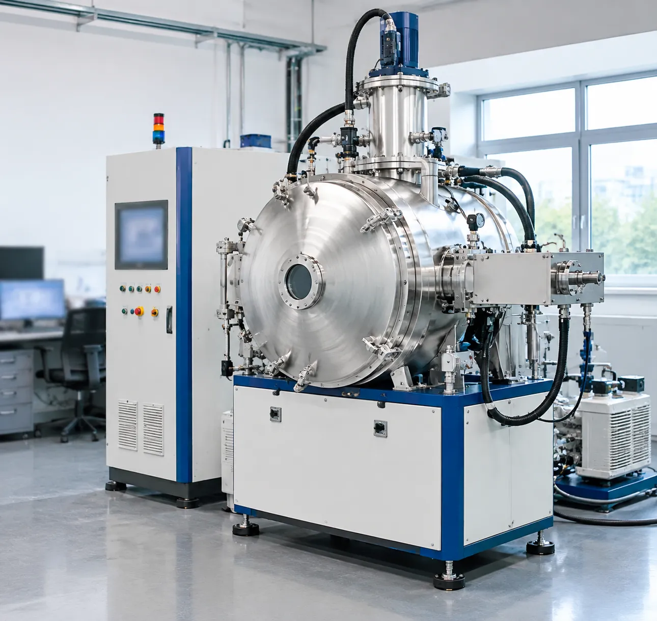
Contamination-Free Molybdenum and Tungsten Hot Zone Architecture
Standard carbon-insulated chambers risk vapor-phase carbon transfer, causing devitrification and dark discoloration in high-purity fused silica. We eliminate this issue completely by utilizing an all-metal hot zone design:
-
- Refractory Metal Elements: Pure molybdenum or tungsten heating grids eliminate volatile impurities during high-temperature cycles up to 1700°C–2000°C.
- Layered Radiation Shielding: Multi-layer molybdenum and stainless steel radiation shields replace conventional graphite felts, preventing particulate dusting and outgassing.
- Clean Structural Support: High-grade ceramic and refractory metal standoffs isolate the workpiece, maintaining optical clarity and chemical purity in the sintered quartz body.
Multi-Stage High-Performance Vacuum Pumping Systems
Rapid pump-down cycles and deep ultimate vacuum levels are critical to degassing silica matrices prior to pore closure. Our high-vacuum architecture features:
-
- Pumping Packages: A robust combination of rotary vane or dry scroll backing pumps, paired with high-throughput Roots blowers and turbomolecular or diffusion pumping systems.
- Deep Base Pressure: Rapid evacuation down to $10^{-3}$ Pa to $10^{-5}$ Pa ensures complete evacuation of trapped atmospheric gases and volatiles.
- Automated Valving: High-vacuum pneumatic gate valves protect the high-vacuum stages against sudden atmospheric exposure or chamber pressure spikes.
Precision Thermal Management and Multi-Zone Temperature Uniformity
Silica glass is sensitive to thermal shock and localized hot spots during vitrification. Our engineering team designs multi-zone heating arrays to guarantee strict temperature uniformity across the entire usable hot zone volume:
-
- Multi-Zone Control: Independent PID control loops compensate for end-loss radiation, keeping thermal variations within ± 3 °C across the workload.
- Ramp Control: Ultra-smooth ramp rates prevent thermal stress fractures in bulky quartz ingots or porous preforms. Detailed profiling parameters mirror the advanced control strategies discussed in our vacuum brazing furnace temperature guide and settings.
- Precision Thermocouples: S-type and B-type calibrated thermocouples, backed by non-contact optical pyrometers for ultra-high temperature tracking.
Industrial PLC Automation and Integrated Safety Interlocks
We integrate commercial-grade industrial automation into every thermal processing vacuum furnace to guarantee process reliability and protect valuable customer workloads:
| Subsystem | Standard Configuration | Operating Advantage |
|---|---|---|
| Control Architecture | Siemens or Allen-Bradley PLC with industrial touch HMI | Recipe storage, automatic cycle execution, and historical data logging |
| Process Interlocks | Water flow, over-temperature, and vacuum thresholds | Auto-shutdown and work-holding safety routines in the event of utility drop |
| Atmospheric Control | Mass flow controllers (MFC) for inert purge (Ar, $N_2$) | Controlled positive-pressure backfilling and partial-pressure processing |
| Emergency Protocols | Fail-safe pneumatic valve closures and fast gas quench | Rapid protection against power interruptions and process deviations |
Comprehensive Technical Specifications Matrix
Our direct sales silica vacuum sintering furnace lineup delivers predictable thermal dynamics, contamination-free hot zones, and reliable atmosphere integrity across both batch R&D and continuous high-volume production.
For teams planning facility footprints and budgeting across different production scales, our vacuum furnace cost and price guide by capacity outlines standard sizing benchmarks alongside these engineering baselines.
| Specification Parameter | Standard Lab / Pilot Scale | Medium Production Scale | Heavy Industrial Production |
|---|---|---|---|
| Effective Hot Zone (W×H×D) | 200 × 200 × 300 mm | 450 × 450 × 600 mm | 800 × 800 × 1200 mm |
| Usable Volume | 12 Liters | 121 Liters | 768 Liters |
| Max Operating Temp | 1700°C (3092°F) | 1750°C (3182°F) | 1800°C (3272°F) |
| Continuous Working Temp | 1600°C (2912°F) | 1650°C (3002°F) | 1700°C (3092°F) |
| Thermal Uniformity | ±3°C | ±5°C | ±5°C |
| Ultimate Cold Vacuum | 5.0 × 10⁻⁴ Pa (Diffusion/Turbo) | 5.0 × 10⁻⁴ Pa (Diffusion/Turbo) | 5.0 × 10⁻³ Pa (Roots/Rotary) |
| Helium Leak Rate | < 1.0 × 10⁻⁹ Pa·m³/s | < 1.0 × 10⁻⁹ Pa·m³/s | < 5.0 × 10⁻⁹ Pa·m³/s |
| Heating Elements | Molybdenum / Tungsten mesh | Molybdenum / Tungsten rod | Tungsten / Graphite (clean-shielded) |
Effective Hot Zone Volumes and Chamber Sizing
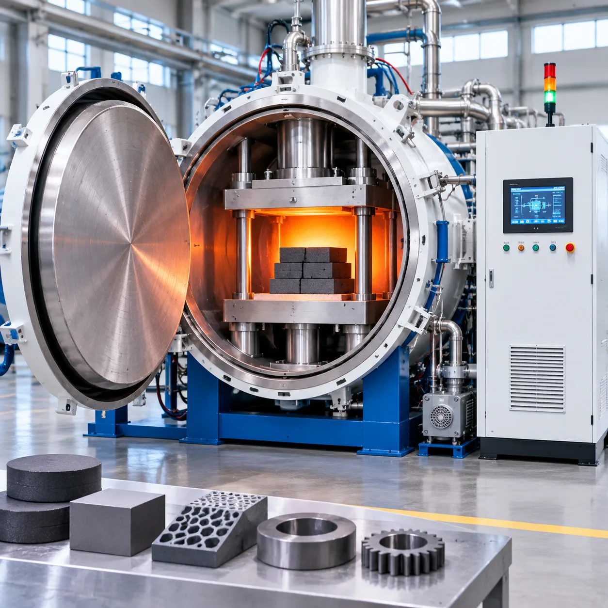
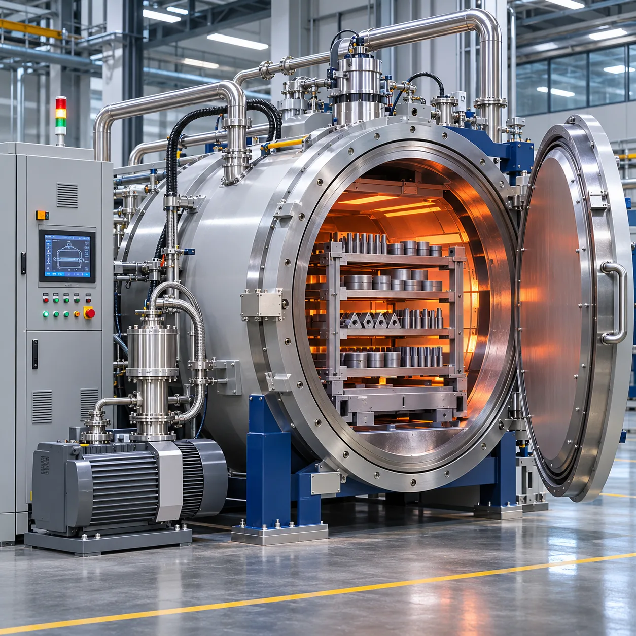
Our standard configurations feature horizontal front-loading and vertical bottom-loading geometries. Hot zones utilize rigid metallic or composite heat shields engineered specifically to avoid cross-contamination:
-
- Compact Form Factors: 12L to 45L hot zones optimized for optical quartz coupons, high-purity laser glass testing, and specialized laboratory sintering.
- Volume Manufacturing Layouts: Scalable chamber envelopes from 120L to over 1,000L, configured with reinforced hearth supports designed to hold heavy silica crucibles and preform tooling up to 1,500 kg.
Operating Temperature Ranges and Heating Ramp Rates
Precision thermal control avoids thermal shock during quartz phase changes:
-
- Ramp Rates: Fully adjustable from 1°C/min up to 20°C/min under full vacuum or inert partial pressure.
- Multi-Zone Trim: Independent SCR power controllers adjust power across top, middle, and bottom heating zones, maintaining tight thermal uniformity across the entire soaking cycle.
- Controlled Cooling: Integrated fast-cooling loops with inert gas circulation reduce turnaround times between batches without risking thermal breakage.
Ultimate Vacuum Levels and Helium Leak Rates
Achieving bubble-free silica matrix densification requires total evacuation of entrapped air and volatile binders:
-
- High-Vacuum Pumping Stacks: Multi-stage pumping setups combine dry screw backing pumps with high-throughput Roots blowers and molecular turbomolecular or diffusion pumps.
- Leak Integrity: Every chamber is verified prior to dispatch using a calibrated helium mass spectrometer, maintaining a baseline leak-up rate of less than 0.5 Pa/h over extended hold periods.
Atmospheric Gas Flow Controls and Utility Demands
-
- Process Gas Dosing: Integrated mass flow controllers (MFC) provide regulated delivery of high-purity Argon, Nitrogen, or Hydrogen-mix gases for tailored sintering cycles.
- Partial Pressure Control: Closed-loop throttling valves hold chamber pressure precisely between 10 Pa and 100 kPa during binder volatilization and outgassing stages.
- Utility Connections: Standard configurations require 3-phase industrial power (380V to 480V, 50/60 Hz), closed-loop cooling water supply (0.2–0.4 MPa at ≤25°C), and pneumatic air supplies at 0.6 MPa for failsafe valve operation.
Key Industrial Applications for Silica Vacuum Sintering
| Application Sector | Process Target | Key Thermal Processing Advantage |
|---|---|---|
| Semiconductor Quartzware | Dense, bubble-free crucibles and carrier rings | Eliminates micro-voids and surface devitrification |
| Optical Fiber Preforms | Vitrification of silica soot bodies | Rapid outgassing and uniform hydroxyl group removal |
| Technical Ceramics (SFS) | High-density fused silica shapes and nozzles | High thermal shock resistance with tight dimensional tolerance |
| Ceramic Injection Molding | Net-shape silica parts debinding and sintering | Clean binder extraction without carbon contamination |
Semiconductor Quartzware and Consumable Components
In modern semiconductor fabrication, component contamination directly lowers wafer yield. We configure our furnaces to process quartz diffusion tubes, wafer carriers, flange assemblies, and plasma etch rings. Sintering under high vacuum removes entrapped gas species, ensuring consistent wall thickness, high mechanical integrity, and complete optical transmission.
Optical Fiber Soot Preforms and High-Purity Fused Silica
Vitrifying synthetic silica soot into transparent preforms requires strict vacuum control to strip residual moisture and volatile contaminants. Our vacuum sintering furnace systems maintain clean, leak-tight processing zones that prevent seed formation and ensure uniform refractive index profiles throughout the core and cladding bodies.
High-Density Sintered Fused Silica (SFS) and Technical Ceramics
SFS components serve in high-temperature metal casting, solar crucible production, and precision aerospace radomes. By utilizing our high-temperature sintering furnace configurations, production teams achieve near-theoretical density without premature crystallization. The resulting material maintains an exceptionally low thermal expansion coefficient and high thermal shock resistance.
Ceramic Injection Molding (CIM) Debinding and Sintering
Producing complex, small-scale silica parts via powder injection molding demands a balance of gradual thermal debinding and consolidation. We engineer integrated thermal cycles that extract organic binders cleanly before transitioning to peak sintering temperatures, preventing structural distortion, blistering, or unwanted carbon residue in finished ceramic components.
Factory Options & Custom Engineering Configurations
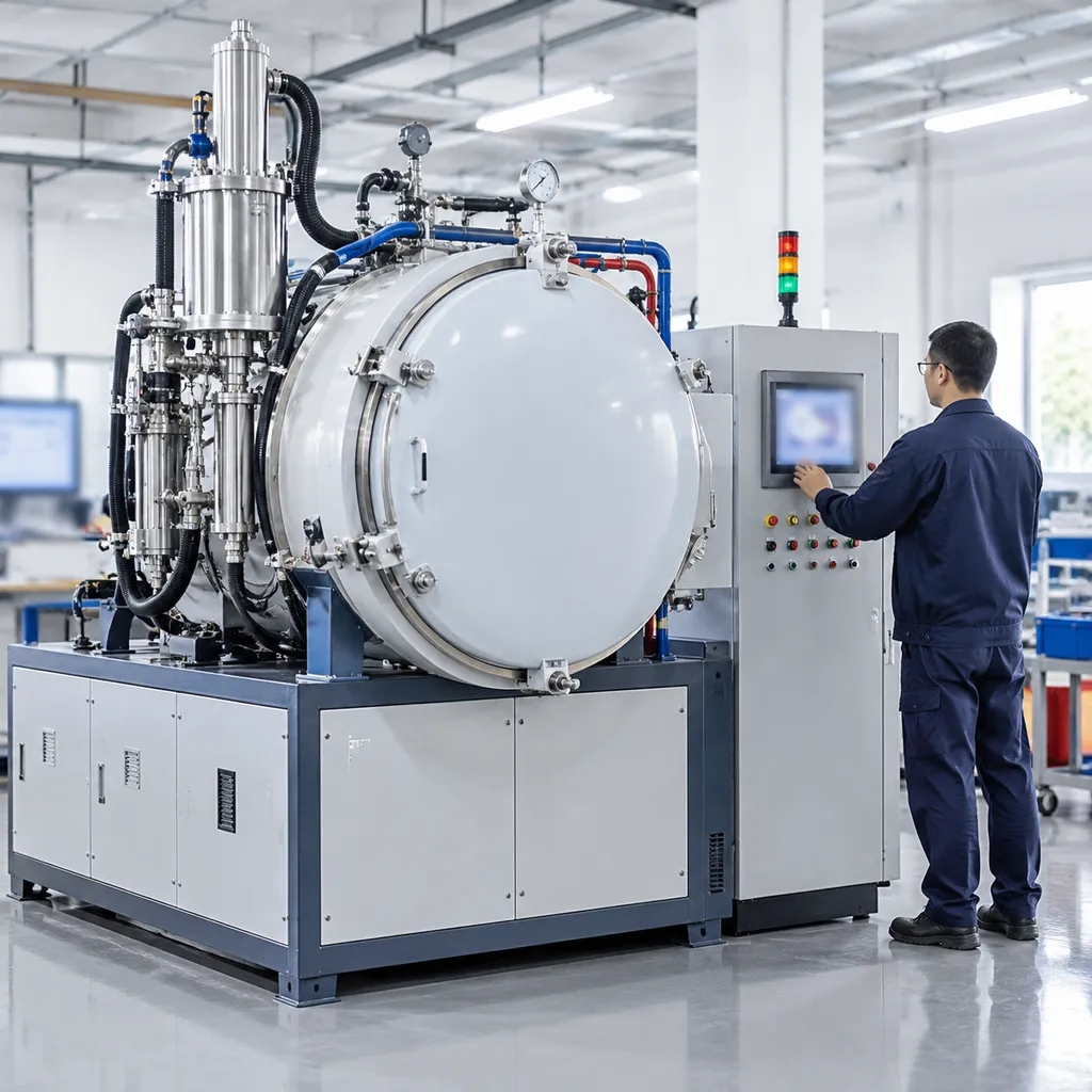
Every production floor faces distinct thermal profile demands and footprint limits. When discussing sales silica vacuum sintering furnace systems with our partners, we configure core architecture to match specific throughput targets, part geometries, and cleanroom requirements through our custom design and engineering solutions.
Horizontal Front-Loading vs. Vertical Bottom-Loading Layouts
Choosing between horizontal and vertical configurations comes down to part geometry, loading ergonomics, and structural deformation risks during high-temperature dwell cycles.
| Configuration | Best Suited For | Loading Mechanism | Key Advantage |
|---|---|---|---|
| Horizontal Front-Loading | Standard trays, crucible batches, rectangular plates | Manual shelf slide or automated cantilever loader | Small footprint, simple access, lower capital cost |
| Vertical Bottom-Loading | Long tubes, large cylindrical boules, heavy quartz preforms | Motorized hydraulic bottom elevator | Zero thermal sagging, balanced radial heat, uniform batch lift |
For facilities handling large quartz ingots or vertical draw bodies, our top-loading vacuum furnace for high-temperature processing provides an ultra-stable foundation that prevents load shifting and uneven thermal stress.
Integrated Binder Burnout Traps and Condensation Units
Processing green bodies formed via ceramic injection molding or gel casting requires proactive binder removal before high-vacuum sintering begins. We install multi-stage effluent mitigation systems directly into the exhaust path:
-
- Heated Exhaust Lines: Prevents volatile wax, PEG, or polymer condensates from solidifying inside vacuum piping.
- Liquid-Cooled Condensation Traps: Captures heavy hydrocarbon chains safely before they reach the main valve manifold.
- Chilled Multi-Stage Filtration: Protects mechanical pumps and high-vacuum diffusion or turbomolecular units from hydrocarbon varnish.
- Automated Burnout Vent Cycles: Sweeps decomposed organics out under a gentle carrier gas purge to keep the hot zone carbon-free.
Multi-Channel Mass Flow Controlled Partial Pressure Dosing
Preventing silica reduction and silica-carbon reactions at peak sintering temperatures requires strict gas dynamics. We build precise gas management directly into the vacuum sequence:
-
- MFC-Regulated Gas Lines: Independent channels for high-purity argon, nitrogen, and hydrogen mixes.
- Controlled Partial Pressure Range: Regulates continuous inert flow from 10 Pa up to 1,000 Pa to suppress SiO vapor formation.
- Closed-Loop Pressure Feedback: Capacitance manometers link directly with the automated control loop to hold chamber pressure flat regardless of outgassing spikes.
- Directional Atmosphere Flushing: Gas distribution rings inject process gases evenly across the load volume, sweeping micro-void outgassing clear of sensitive optics.
Manufacturing Standards, Quality Control, and Testing
Every unit in our sales silica vacuum sintering furnace line undergoes rigorous factory acceptance testing (FAT) before dispatch. When processing fused quartz and high-purity silica matrices, microscopic vacuum leaks or temperature gradients lead straight to devitrification and ruined batches. We eliminate these risks on the factory floor through systematic validation protocols.
Helium Mass Spectrometer Vacuum Leak Certification
Vacuum integrity dictates product purity. We test each chamber, weld seam, flange, and feedthrough using multi-point helium mass spectrometry:
Global and Local Sniffing: Testing down to standard leak rates below 1 × 10⁻⁹ mbar·L/s.
Pressure Rise Verification: Measuring outgassing rates over 24-hour cycles to guarantee baseline vacuum stability before heating.
Seal Reliability: Dual-elastomer and metal-seal joints checked under repeated mechanical cycling.
Multi-Point Thermal Uniformity Surveys (FAT Protocols)
Precise sintering of silica requires uniform heat distribution across the entire workspace. Our engineering team validates hot zones using multi-couple surveys compliant with AMS 2750 standards:
Multi-Point Arrays: 9-point to 15-point thermocouple grids placed throughout the effective working volume.
Ramp and Soak Testing: Uniformity evaluated across the full thermal ramp, maintaining tight tolerances at peak temperatures up to 1700°C.
Data Transparency: Customers receive complete digital FAT logs, temperature survey charts, and heating curves prior to equipment sign-off.
ISO 9001 and CE Compliance Standards
We manufacture all our thermal systems under strict quality management systems. Our factory operations adhere to certified quality certifications, ensuring standardized mechanical assembly, safety protocols, and traceable component sourcing.
-
- ISO 9001 Audited Workflows: Controlled fabrication from raw steel cutting to final PLC programming.
- CE Compliance: Full adherence to European Low Voltage and Machinery Directives, complete with emergency over-temperature circuits, fail-safe pneumatic interlocks, and vacuum safety relief valves.
Direct Factory Sales Terms and Technical Support
When sourcing industrial thermal equipment, eliminating middleman markups gives your facility the highest return on investment. Through our direct manufacturer channel, we handle every stage of your order—from engineering review to production sign-off. As a thermal processing vacuum furnace supplier, we provide full transparency across contract negotiation, warranty coverage, and scheduled delivery times for every custom build. Explore our factory-direct vacuum furnace solutions to align production requirements with exact equipment build specifications.
Direct Manufacturer Pricing and Commercial Terms
We structure procurement contracts to fit global project logistics, cash-flow cycles, and plant timelines. We accommodate three standard international trade options:
| Commercial Term | What We Handle | Buyer Responsibilities |
|---|---|---|
| FOB (Free on Board) | Export packing, factory loading, inland transport, and China export clearance | Ocean freight, import customs, port fees, and final site transport |
| CIF (Cost, Insurance & Freight) | All FOB obligations plus ocean freight and marine transit insurance to destination port | Destination port handling, local import clearance, duties, and offloading |
| DDP (Delivered Duty Paid) | End-to-end transport, port clearances, import duties, and delivery straight to your factory floor | Unloading facilities and site hookup readiness |
Each sales silica vacuum sintering furnace contract includes dedicated milestone tracking, from down payment to Factory Acceptance Testing (FAT) approval.
Turnkey Global Installation and Operator Training Programs
Commissioning a high-vacuum thermal system demands precision alignment and vacuum-tight utility integration. Our field engineering crew manages deployment directly at your facility through our global field service network.
-
- On-Site Installation Supervision: Mechanical placement, vacuum piping verification, water cooling loops, and electrical cabinet tie-ins.
- Cold & Hot Commissioning: Vacuum pump-down leak tests, baseline bake-outs, and initial process cycle runs.
- Hands-On Operator Training: Step-by-step instruction covering PLC recipe configuration, safety interlock troubleshooting, and preventive maintenance routines.
Long-Term Spare Parts Availability and Consumable Kits
Unplanned downtime ruins sintering runs and risks valuable quartz stock. We stock critical components for fast dispatch to keep your hot zones and vacuum systems running continuously:
-
- Hot Zone Consumables: Molybdenum and tungsten heating elements, radiation shields, hearth plates, and load-support pins.
- Vacuum Seals & Hardware: Pre-formed Viton O-rings, high-temp door gaskets, sight glasses, and vacuum flange clamps.
- Instrumentation & Pumping Supplies: Type S/B thermocouples, vacuum gauge heads, roughing pump oils, and diffusion pump fluids.
Frequently Asked Questions About Silica Vacuum Sintering Furnaces
How does vacuum depth prevent devitrification and bubble defects in quartz?
Deep vacuum levels directly eliminate residual gas molecules trapped inside the porous green body before pore closure occurs. In a standard sales silica vacuum sintering furnace configuration, operating at fine vacuum pressures removes volatile hydroxyl groups (OH-) and entrapped atmosphere. This prevents Cristobalite nucleation—the phase transformation responsible for devitrification—and yields fully transparent, bubble-free fused quartz components.
Which hot zone element is best to prevent carbon contamination in silica?
For high-purity silica glass and semiconductor quartz processing, an all-metal hot zone is mandatory. We configure these systems with high-purity molybdenum or tungsten heating elements and metallic radiation shields:
| Hot Zone Construction | Carbon Risk | Max Clean Temp | Recommended Application |
|---|---|---|---|
| All-Metal (Molybdenum / Tungsten) | Zero | Up to 2000°C | Semiconductor quartz, optical preforms, high-purity silica |
| Graphite Heating / Felt Insulation | High (CO/CO₂ formation) | Up to 2200°C | Non-optical technical ceramics only |
Using all-metal hot zones prevents the carbon vapor reaction that turns clear silica hazy and reduces structural integrity.
Can one furnace handle both debinding and high-temperature sintering?
Yes. Our combined debinding and sintering architectures feature dedicated wax/binder condensation traps and controlled carrier-gas purge cycles. For operations requiring continuous high-throughput separation of thermal processing steps, our engineering team also configures multi-stage layouts similar to our triple-chamber vacuum furnace to segregate binder burnout from high-vacuum vitrification.
What are the typical lead times and utility requirements for installation?
Lead times and facility requirements depend on chamber size and pumping package options:
-
- Production Lead Time: Typically 10 to 14 weeks for standard models; 16 to 20 weeks for fully customized high-capacity systems.
- Electrical Supply: 3-phase industrial power (380V/440V/480V, 50/60 Hz) scaled to hot zone size, ranging from compact 50 kW units up to high-capacity 200kW vacuum sintering furnace installations.
- Cooling Water Loop: Closed-circuit deionized/industrial water at 0.2 to 0.4 MPa pressure.
- Process Gas: High-purity Argon or Nitrogen (minimum 99.999% purity) regulated at 0.2 MPa for partial-pressure sintering and rapid gas cooling.