Formula details
Product Details
Overview
What Is a Triple-Chamber Vacuum Furnace?
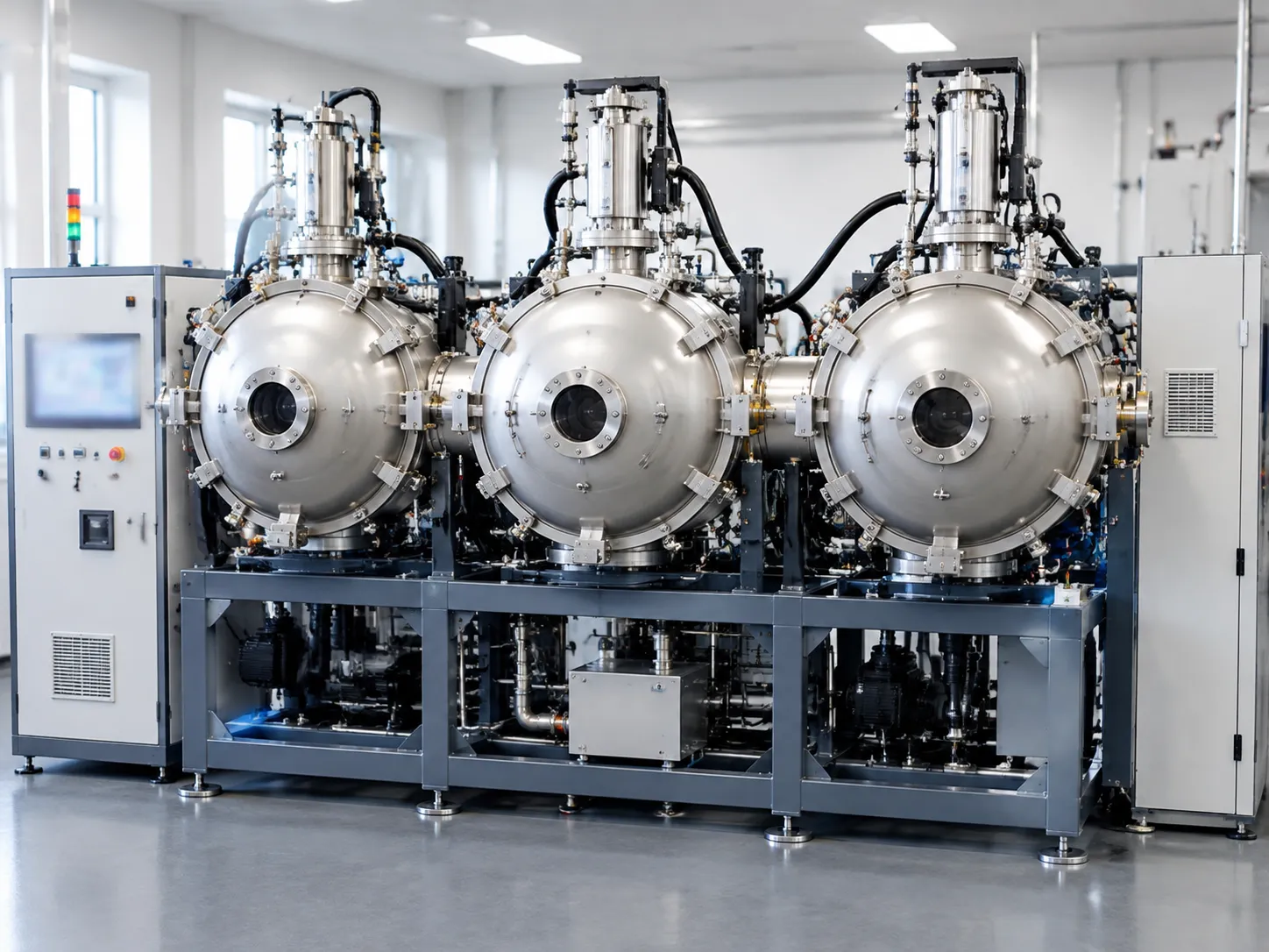
A triple-chamber vacuum furnace is an advanced industrial vacuum heat treatment system engineered for high-throughput, continuous-batch thermal processing. By separating the thermal cycle across three dedicated, isolated zones, we eliminate the operational bottlenecks and severe energy losses inherent in conventional single-chamber batch furnaces.
Our engineering architecture allows distinct metallurgical stages—heating, workload transfer, and rapid quenching—to occur simultaneously under controlled vacuum environments.
[ Heating Chamber ] <---> [ Intermediate Transfer Chamber ] <---> [ Quenching/Cooling Chamber ]
(Continuous Hot) (Vacuum Interlock/Transport) (Gas/Oil Quench Zone)
Three-Chamber System Configuration
Our triple-chamber configuration integrates three distinct functional modules connected by high-vacuum isolation systems:
-
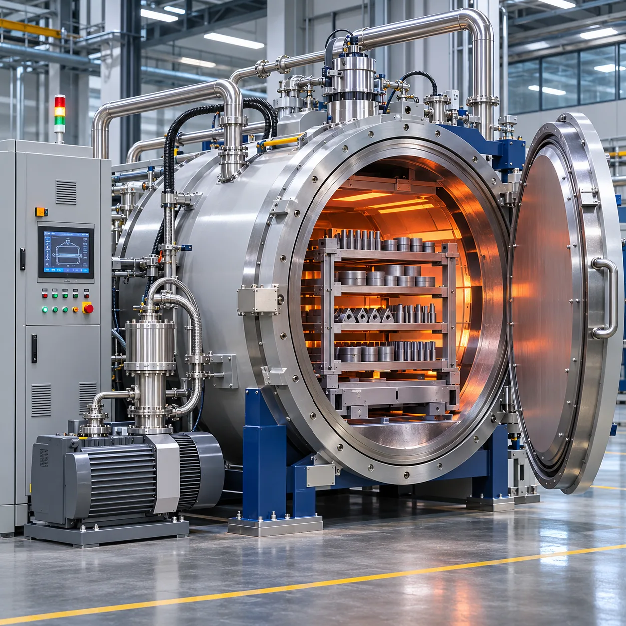
- Heating Chamber (Hot Zone): Dedicated exclusively to austenitizing, annealing, brazing, or sintering. Because it remains under vacuum and near operating temperatures continuously, it avoids the energy-intensive heating-and-cooling cycles of standard furnaces.
- Vacuum Transfer Chamber (Transition Module): An intermediate, high-vacuum handling hub equipped with a motorized, multi-axis drive system. It moves workloads rapidly between chambers without breaking the internal vacuum environment.
- Cooling and Quenching Chamber: An isolated zone customized for specific metallurgical transformation needs, featuring either multi-directional high-pressure gas quenching (up to 20 bar) or an integrated vacuum oil quench tank.
Multi-Stage Continuous Operating Cycle
By physically decoupling the thermal stages, our triple-chamber vacuum furnace runs a synchronized, multi-workpiece cycle:
-
- Staged Workpiece Loading: A cold batch enters the intermediate chamber and is pumped down to the target vacuum level.
- Rapid Vacuum Transfer: The internal gate valve opens, and the automated transfer mechanism loads the batch directly into the pre-heated hot zone.
- Thermal Processing: The primary batch undergoes high-precision soaking while completely isolated from the cooling media.
- Fast Transfer to Quench: Once the soak time concludes, the mechanism shifts the hot workload through the transfer chamber into the quench chamber within seconds.
- Simultaneous Processing: While the first workload cools rapidly in the quenching chamber, a new workload enters the hot zone, maximizing overall equipment effectiveness (OEE).
Vacuum Integrity and Thermal Isolation
Maintaining absolute pressure separation and thermal boundaries between adjacent chambers is critical for metallurgical consistency. We achieve this through robust structural engineering:
-
- Heavy-Duty Vacuum Gate Valves: Pneumatically actuated, water-cooled isolation valves provide a reliable, hermetic seal between the hot zone, transfer module, and quench chamber.
- Independent Pumping Groups: Each chamber features its own dedicated roughing and high-vacuum pumping system (rotary vane, roots, and diffusion/turbomolecular pumps) to prevent cross-contamination and eliminate pressure spikes during transfers.
- Thermal Barrier Protection: Multi-layer thermal insulation packages restrict radiant heat loss within the heating chamber, keeping transfer mechanisms and cooling media thermally isolated.
Main Benefits of a Triple-Chamber Vacuum Furnace
A triple-chamber vacuum furnace transforms conventional batch heat treatment into a high-efficiency, semi-continuous workflow. By decoupling the heating, transfer, and quenching operations into dedicated modules, our multi-chamber engineering eliminates production bottlenecks and maximizes equipment utilization.
Understanding the broader scope of vacuum furnace applications, uses, and benefits helps explain why separating thermal zones delivers unmatched metallurgical and economic advantages.
High-Throughput Performance Summary
| Operational Factor | Single-Chamber Systems | Triple-Chamber Vacuum Furnace | Direct Impact |
|---|---|---|---|
| Cycle Efficiency | Sequential heating and cooling in one vessel | Concurrent multi-stage processing across three zones | 2x to 3x higher batch output |
| Energy Consumption | Repeatedly heats and cools chamber mass | Hot zone stays at operating temperature | Up to 40% lower power consumption |
| Atmosphere Purity | Hot zone exposed to atmosphere during unloading | Permanent vacuum isolation between chambers | Zero oxidation & zero decarburization |
| Material Flow | Intermittent batch pauses | Automated continuous indexing | Consistent production rhythm |
Higher Throughput and Reduced Cycle Times
In standard batch units, the furnace must heat up, soak, quench, and cool down before reloading. Our three-chamber vacuum furnace processes three distinct workloads simultaneously:
Chamber 1: Loading, pre-evacuation, and pre-heating.
Chamber 2: High-temperature soaking and thermal processing under stable vacuum.
Chamber 3: High-pressure gas quenching or oil quenching.
This concurrent processing cuts overall cycle turnaround times drastically, making it the ideal continuous vacuum heat treatment furnace for high-volume manufacturing lines.
Minimized Thermal Loss and Energy Efficiency
Repeatedly heating and cooling the hot zone insulation and heating elements wastes significant electrical energy. In our system architecture:
The vacuum heating chamber remains under steady-state thermal conditions.
Cold loads enter via the transfer module without thermal shock to the elements.
Energy is applied directly to the workload rather than reheating furnace structural walls.
Superior Process Consistency and Temperature Uniformity
Maintaining the main hot zone at continuous operating temperature delivers tightly controlled thermal profiles:
Precision Soaking: Eliminates temperature fluctuations caused by frequent door openings.
Repeatable Metallurgy: Standardized recipe parameters ensure load-to-load hardness and structural uniformity.
Zone Stability: Multi-zone heating elements provide exceptional temperature distribution across every batch.
Clean Surface Quality with Zero Oxidation
Dedicated vacuum isolation valves seal the heating chamber from quench oils, cooling gases, and ambient room air.
No Decarburization: Critical for tool steels, aerospace fasteners, and transmission gears.
Bright Metallic Finish: Workpieces exit the cooling chamber completely clean, eliminating post-heat-treatment pickling, machining, or shot-blasting.
Flexible Production Planning for Continuous Batch Operations
Our automated vacuum furnace systems integrate seamlessly into modernized factory workflows. Plant operators can schedule continuous campaigns with varying recipes, adjust quench parameters per batch, and feed downstream finishing cells without staging delays.
Triple-Chamber Vacuum Furnace System Architecture
Our triple-chamber vacuum furnace systems are engineered with three distinct, dedicated zones configured in-line to deliver maximum thermal efficiency and continuous workflow.
Heating Chamber
Hot Zone / Soaking
↔
Transfer Chamber
Vacuum Isolation & Workpiece Transfer
↔
Quenching Chamber
Gas / Oil Quenching
Vacuum Heating Chamber Design, Element Materials, and Thermal Insulation
The heating chamber operates as a continuously hot thermal zone under high vacuum, engineered to minimize energy consumption:
-
- Heating Elements: Configurable with high-purity curved graphite elements, wide-band molybdenum, or metallic heating alloys depending on process purity requirements.
- Thermal Insulation: Multi-layer rigid graphite board backed by carbon felt, or an all-metal reflective shield package (molybdenum and stainless steel) for ultra-clean processing.
- Multi-Zone Temperature Control: Independent heating zones managed via precision digital controllers to ensure tight temperature uniformity throughout the work envelope.
- Continuous Thermal Envelope: Kept at operating temperature under vacuum, avoiding the thermal expansion and contraction cycles that degrade heating elements in conventional batch furnaces.
Vacuum Transfer Chamber, Rapid Transfer Mechanisms, and Isolation Valves
The center transfer chamber serves as the pressurized and vacuum transition hub between thermal processing and rapid cooling:
-
- Vacuum Gate Valves: Pneumatically actuated, water-cooled vacuum isolation valves seal the hot zone from the quenching sector, preventing oil vapor backstreaming or gas infiltration into the heating module.
- Rapid Transfer Drive: Heavy-duty internal chain drives or pneumatic push-pull transfer forks move workloads between chambers in seconds, keeping exposure times low to eliminate part cooling before quenching.
- Dynamic Vacuum Integrity: Equipped with dedicated auxiliary pumping systems to equalize vacuum levels between chambers before valve opening, preventing pressure shocks and particulate movement.
Cooling and Quenching Chamber Configurations: High-Pressure Gas and Oil Quench
The dedicated quenching module provides fast, uniform metallurgical cooling tailored to your specific alloy requirements:
-
- High-Pressure Gas Quenching (HPGQ): Uses high-velocity gas nozzles with 360-degree radial or top/bottom flow patterns using nitrogen or argon at pressures up to 10–20 bar. While a single-chamber vacuum furnace with high-pressure gas quenching handles one load through every phase, our triple-chamber design allows the quenching cell to cool one workload while another is already heating.
- Vacuum Oil Quenching: Built with an integrated quench oil tank positioned directly beneath the transfer elevator. Includes variable-speed oil agitation impellers, integrated oil heaters, and heat exchangers to ensure uniform flow velocity and predictable core hardness.
- Dual-Quench Modularity: Configurable as an interchangeable system capable of supporting both high-pressure gas cooling and vacuum oil immersion in adjacent processing modules.
Loading, Unloading, and Automated Material Handling Systems
We build our multi-chamber vacuum furnace equipment with fully automated material handling to minimize manual intervention and ensure process safety:
-
- External Charge Cars: Floor-mounted, motorized transfer cars automatically align with loading and unloading ports for seamless charge loading.
- Precision Work Trays: Heavy-capacity, thermal-shock-resistant alloy or graphite fixtures engineered to support heavy part loads without warping under repeated thermal-to-quench transitions.
- Automated Tracking: Industrial sensors, interlocks, and optical positioners coordinate the automated transfer sequence through the PLC to prevent operational collisions or premature valve actuation.
Technical Specifications and Configurable Parameters
Standard Specification Matrix
| Parameter | Standard Range / Capability | Custom Options |
|---|---|---|
| Max Operating Temperature | 1200°C to 1350°C (2192°F to 2462°F) | Up to 1600°C for specialized sintering |
| Temperature Uniformity | ±3°C to ±5°C (AMS 2750 / CQI-9 compliant) | Multi-zone closed-loop trim control |
| Ultimate Vacuum Level | 1 × 10⁻¹ Pa (Mechanical + Roots) | 5 × 10⁻⁴ Pa (Diffusion / Turbo) |
| Leak Rate (Rise Rate) | < 0.05 Pa/h (measured on a clean, dry chamber) | Ultra-high purity seals |
| Quench Gas Pressure | 2 bar to 12 bar absolute (Nitrogen / Argon) | 16 bar / 20 bar high-velocity flow |
| Oil Quench Agitation | Variable-speed directional impellers | Integrated heat exchangers & heaters |
| Batch Load Capacities | 200 kg to 2,500 kg per tray | Custom heavy-duty hearth designs |
Vacuum Pumping Systems and Leak-Rate Control
Our multi-chamber vacuum furnace layouts utilize independent pumping groups for each chamber to prevent cross-contamination and minimize cycle delays:
-
- Independent Evacuation: The heating chamber remains under continuous vacuum while the transfer and cooling chambers pump down independently during part staging.
- Pump Configurations: Multi-stage configurations combine rotary vane or dry screw backing pumps with high-capacity Roots blowers. For high-purity processes, we integrate oil diffusion or turbomolecular vacuum pumps.
- Leak Integrity: All chambers undergo helium mass spectrometer leak testing during assembly, ensuring strict sealing standards and process repeatability.
Heating Zone Control and Thermal Uniformity
We design the heating chamber with multi-zone heating configurations to deliver uniform thermal profiles across dense workloads:
-
- Multi-Zone Trim: Independent PID control loops compensate for end losses, maintaining consistent soaking across the entire usable work zone.
- Element Materials: We configure graphite heating elements, curved graphite tubes, or molybdenum/metallic arrays depending on process cleanliness and temperature requirements.
- Protection Systems: Dual-element thermocouple monitoring, independent over-temperature controllers, and water-cooling interlocks prevent element burnout and load damage.
Cooling Performance and Quench Pressure Control
Rapid heat extraction in the cooling chamber is controlled through high-velocity gas circulation or integrated vacuum oil quenching:
-
- High-Pressure Gas Quenching: Variable-speed aerodynamic blowers paired with 360-degree radial nozzles provide uniform gas distribution, matching the performance profiles of our high-pressure 12-bar gas quenching systems.
- Oil Quench Dynamics: For heavy cross-sections and carburized parts, our oil quench tanks feature variable-speed impellers, automated elevator transfer mechanisms, and precision oil-temperature management.
- Distortion Reduction: Quench pressure and blower speeds can be ramped dynamically to balance core hardness with dimensional stability.
PLC-Based Automation and SCADA Integration
Every system runs on an industrial PLC platform (Siemens or Allen-Bradley) designed for fully automated multi-chamber operation:
-
- Automated Recipe Management: Operators select predefined heat treatment recipes that govern chamber sequencing, pump-down curves, heating rates, hold times, and quench cycles.
- SCADA & MES Connectivity: Native Ethernet/IP and Profinet protocols enable seamless data logging, automated batch tracking, and direct integration with plant-wide manufacturing execution systems.
- Process Traceability: Real-time logging of vacuum levels, power draw, temperature profiles, and transfer timings ensures complete compliance with aerospace and automotive quality audits.
Heat Treatment Processes Supported
Vacuum Hardening and Gas or Oil Quenching
We configure the quenching chamber for either multi-directional high-pressure gas quenching (HPGQ) or integrated vacuum oil quenching. Rapid, automated workpiece transfer from the hot zone into the quench chamber preserves surface chemistry, prevents pre-cooling, and eliminates decarburization on tool steels, die steels, and structural alloys.
-
- Gas Quenching: Uses high-velocity nitrogen or argon up to 20 bar for minimal part distortion.
- Oil Quenching: Delivers immersion transfer speeds under 10 seconds into agitated, temperature-controlled quench oil for deep-hardening steels.
Vacuum Annealing and Stress Relieving
Our vacuum annealing furnace systems eliminate surface oxidation and scale formation on critical alloy parts. We utilize uniform heating cycles and controlled slow cooling to relieve residual machining stresses, restore ductility, and prepare materials such as titanium alloys, stainless steels, and superalloys for downstream processing.
Precision Vacuum Tempering
Achieving the exact balance of hardness and toughness requires tight temperature uniformity. Our systems execute precision tempering cycles under fine vacuum or partial pressure inert atmospheres, preventing discoloration and preserving clean part finishes after hardening.
High-Purity Vacuum Brazing
By maintaining high vacuum levels and low leak rates, our vacuum brazing furnace design allows for flux-free joining of complex assemblies, including heat exchangers, aerospace manifolds, and turbine components. Uniform radiant heat guarantees even capillary flow of braze filler metals across dissimilar and high-temperature alloys.
Vacuum Sintering for Powder Metallurgy and Carbides
We engineer multi-chamber systems to support solid-state and liquid-phase sintering for powder metallurgy (PM), metal injection molded (MIM) parts, and cemented carbide inserts. Dedicated temperature control stages ensure clean binder removal, pore closure, and full material densification without oxidation. For specialized melting and raw alloy synthesis prior to sintering, our industrial induction vacuum furnace for high-purity alloys serves as a complementary upstream solution.
Degassing and Controlled Atmosphere Processing
The continuous vacuum heat treatment furnace removes entrapped gases—such as hydrogen, oxygen, and nitrogen—from refractory metals and critical forgings. When processing alloys with high vapor-pressure elements (such as chromium or manganese), our systems introduce automated partial-pressure inert gas to suppress alloy evaporation and maintain surface chemistry integrity.
Industrial Applications and Use Cases
Aerospace and Aviation Components
Structural airframe parts, landing gear hardware, and turbine sections require strict vacuum integrity and zero contamination. We configure our multi-chamber systems to process titanium alloys, nickel-based superalloys, and high-strength steels. The isolated thermal cycles eliminate atmospheric exposure, preventing hydrogen embrittlement and maintaining baseline fatigue limits.
Automotive Powertrain, Gears, and Shafts
Automotive suppliers rely on continuous processing to meet high-volume production schedules without sacrificing case uniformity:
Transmission Gears & Pinions: Gas or oil quenching with minimal distortion to reduce downstream grinding costs.
Drive Shafts & Axles: Uniform through-hardening and core toughness across high-tonnage batches.
Fuel Injection Hardware: Clean vacuum surface processing that leaves micro-orifices free of scale or residue.
Our multi-stage systems integrate directly into modern industrial heat treatment lines to maintain a non-stop production flow.
Tool, Die, and High-Speed Steel (HSS) Manufacturing
For hot-work, cold-work, and high-speed tool steels (such as D2, H13, and M2), uniform heating and controlled cooling rates are essential. Our multi-chamber layout allows precision preheating in the entry zones before moving to high-temperature austenitizing and high-pressure gas quenching. This multi-step process minimizes thermal shock, prevents cracking, and preserves critical dimensional tolerances on intricate stamping dies and extrusion tooling.
Medical Devices and Surgical Instruments
Medical-grade stainless steels, titanium implants, and precision surgical instruments require an ultra-clean processing environment. Operating under high vacuum levels ensures parts exit the cooling chamber bright, clean, and free of surface oxides or decarburization, eliminating the need for aggressive post-treatment pickling or polishing.
Powder Metallurgy, Carbide Inserts, and Wear Parts
We supply specialized vacuum systems for sintering, degassing, and hardening wear-resistant materials:
Cemented Carbide Inserts: Uniform binder distribution and precise temperature control for consistent hardness.
Sintered Structural Parts: High-density compaction support with controlled cooling stages.
Wear Plates & Bushings: Heavy-duty cycle stability with repeatable metallurgical outcomes.
Precision Machinery and Specialty Alloy Manufacturing
From hydraulic pump components and industrial valve bodies to high-load bearing rings, our three-chamber vacuum systems handle diverse specialty alloys. Our programmable cooling and heating recipes give plant operators the flexibility to switch between different alloy profiles while maintaining automated, continuous throughput.
Triple-Chamber vs. Single-Chamber and Double-Chamber Furnaces
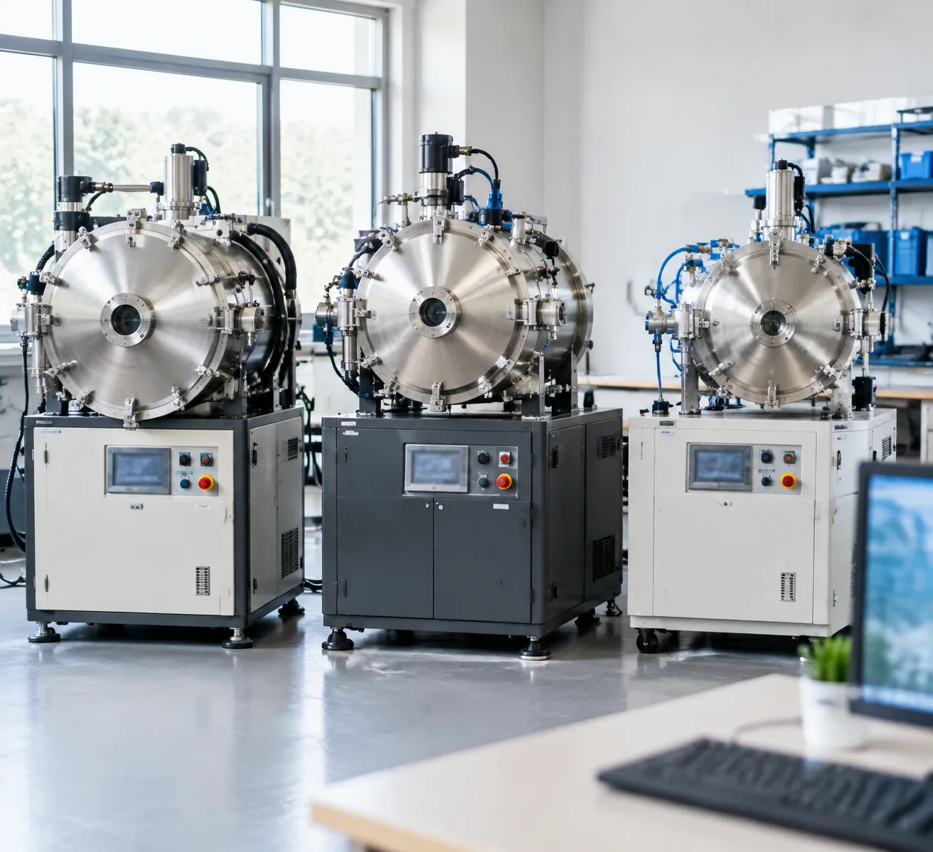
Choosing between single-chamber, double-chamber, and a triple-chamber vacuum furnace comes down to balancing production volume, cycle efficiency, and utility consumption. While conventional batch systems serve low-volume or variable cycles well, multi-chamber systems unlock continuous production capabilities for high-throughput operations.
Multi-Stage Layout vs. Single-Chamber Batch Operation
In a standard single-chamber configuration—such as a conventional universal batch chamber vacuum aluminum brazing furnace—heating, soaking, and quenching occur within the same vessel. This forces the hot zone insulation and heating elements to cool down and reheat during every cycle, creating substantial thermal lag and elevated energy consumption.
A three-chamber vacuum furnace eliminates this thermal cycling bottleneck by dedicating separate, isolated vessels to each phase:
-
- Heating Chamber: Remains continuously at operating temperature under steady vacuum, protecting hot zone elements from thermal shock.
- Transfer Chamber: Serves as an intermediate vacuum transition airlock that shifts workloads rapidly without exposing the hot zone to the external atmosphere or quenching media.
- Quenching Chamber: Operates independently to deliver rapid oil or high-pressure gas cooling while the heating chamber immediately begins processing the next workload.
Throughput, Cycle Time, and Thermal Efficiency Differences
By isolating processing stages, a continuous vacuum heat treatment furnace processes multiple workloads simultaneously across different stages of the thermal cycle, significantly reducing overall turnaround time.
| Performance Metric | Single-Chamber Furnace | Double-Chamber Furnace | Triple-Chamber Vacuum Furnace |
|---|---|---|---|
| System Architecture | Combined heat and quench vessel | Separate heat and quench chambers | Dedicated heating, transfer, and quenching chambers |
| Thermal Efficiency | Lower (hot zone reheated each batch) | Moderate (heating chamber stays hot) | Highest (minimal thermal loss during rapid transfer) |
| Cycle Time | Longest (full heating and cooling cycle per load) | Intermediate turnaround | Shortest (simultaneous multi-batch processing) |
| Production Throughput | Batch sequential processing | Staggered two-stage workflow | Continuous high-volume production output |
| Cross-Contamination Risk | Higher (quench vapors enter hot zone) | Low (direct transfer interface) | Zero (isolated transfer lock blocks vapor migration) |
Comparative Selection Criteria Based on Production Volume and Workflow
Our engineers evaluate several operational parameters when recommending a furnace architecture for your facility:
-
- Single-Chamber Systems: Best suited for low-volume, high-mix production runs, highly variable metallurgical recipes, or small batch pilot lines.
- Double-Chamber Systems: Ideal when you require faster quenching turnaround than a single-chamber unit can provide, but floor space or initial capital investment is limited.
- Triple-Chamber Systems: Recommended when:
- Your operation requires non-stop, high-volume production with tight delivery schedules.
- You need to eliminate energy waste caused by repeatedly heating and cooling the hot zone structure.
- Your process requires complete physical separation between quenching media (oil or gas) and clean heating elements to guarantee surface purity.
- Your workflow requires fully automated tray transfer mechanisms integrated with automated plant logistics.
Custom Engineering Options for Triple-Chamber Vacuum Furnaces
Tailored Hot Zone & Load Configurations
We design the heating and cooling chambers around your parts and batch requirements to prevent underutilized volume and excessive power consumption:
-
- Custom Work Zone Volumes: Scaled to fit specific part envelopes, from compact tooling batches to long shafts and heavy structural gears.
- Load Capacities: Heavy-duty hearths engineered for gross load capacities ranging from several hundred kilograms to multi-ton industrial charges.
- Fixture Design: Dedicated carbon-composite (CFC) or high-temperature molybdenum and alloy fixturing to maximize packing density and prevent thermal distortion.
Through our dedicated custom design and engineering process, we calculate exact thermal mass profiles to ensure uniform heat penetration and efficient cycle times.
Heating Element and Insulation Packages
We select hot zone construction materials based on process purity, maximum operating temperature, and atmosphere compatibility:
| Component / System | Available Material Options | Typical Application |
|---|---|---|
| Graphite Hot Zones | High-purity graphite elements, rigid graphite felt, carbon-composite shielding | General vacuum hardening, carburizing, high-volume production |
| All-Metal Hot Zones | Molybdenum, tungsten, and stainless steel radiation shields | Cleanroom aerospace parts, medical devices, ultra-pure vacuum brazing |
| Metallic Heating Elements | Nickel-chromium (NiCr) or molybdenum disilicide (MoSi2) | Low-to-medium temperature processing and specialized atmospheres |
Quench System Customization
We tailor the cooling chamber configuration to your specific hardenability and distortion-control requirements:
-
- High-Pressure Gas Quenching: 2 bar to 20 bar cooling using nitrogen, argon, or helium with 360-degree radial or alternating directional nozzles to minimize part warpage.
- Vacuum Oil Quenching: Integrated oil tanks equipped with multi-speed, variable-frequency agitation impellers, oil heating/cooling loops, and directional baffles for deep-hardening alloy steels.
- Combined Multi-Quench Capabilities: Hybrid configurations supporting both gas and oil quenching paths within a single multi-chamber layout.
Factory Automation, Footprint & MES Integration
To integrate seamlessly into your workflow, we build automated vacuum furnace systems that link directly to facility-wide networks:
-
- Automated Material Handling: Motorized external charge cars, roller hearth transfers, and pneumatic internal pusher/puller mechanisms for continuous, hands-free batch transitions.
- Footprint Optimization: Straight-line (in-line), U-shaped, or L-shaped chamber layouts designed to fit existing plant floor constraints.
- Plant-Level Connectivity: Full system and process integration using industrial PLC and SCADA platforms compatible with plant MES, enabling automated recipe dispatch, process logging, and AMS 2750/CQI-9 data compliance.
- Utility & Electrical Matching: Built to global electrical codes (NEC, IEC, CE) with tailored cooling water manifolds, closed-loop emergency water systems, and facility-matched gas storage skids.
Equipment Quality, Safety Systems, and Reliability
Integrated Safety Interlocks and Emergency Stop Systems
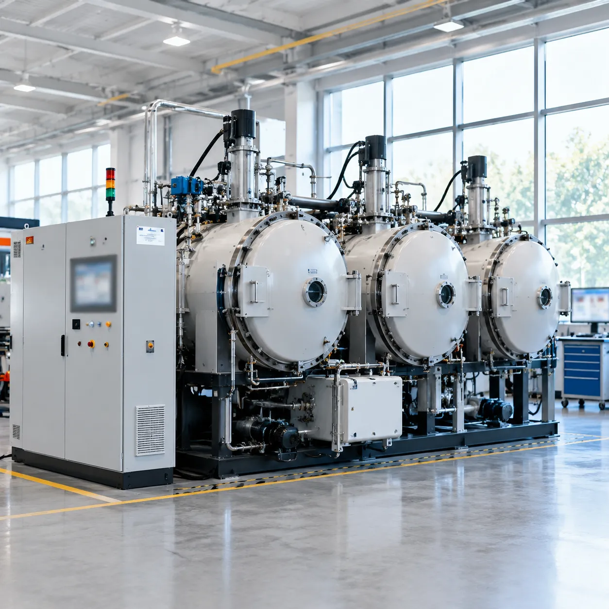
Multi-chamber systems involve coordinated mechanical movement, high temperatures, high-pressure gas, and oil quench media. Our control architectures incorporate multi-layered hardware and software interlocks to protect personnel and workloads:
-
- Chamber Isolation Protection: Mechanical and electrical interlocks prevent isolation gate valves from opening if pressure differentials, atmosphere mismatches, or temperature thresholds exceed safe limits.
- Over-Pressure and Pressure Relief Devices: Quenching and transfer sections feature dual-stage mechanical relief valves and burst discs to safely vent over-pressure events during high-pressure gas quenching.
- Fail-Safe Atmosphere Control: Automated inert gas purge and backfill routines automatically activate during unexpected power loss, cooling water flow drops, or vacuum loss.
- Emergency Stop Network: Hardwired E-stop buttons are located across the main control console, loading stations, transfer drives, and maintenance access points for immediate system-wide shutdown.
Factory Acceptance Testing (FAT) and Helium Leak Detection
We validate every industrial vacuum furnace under full operational simulation before shipping. Our production processes adhere to rigorous international standards and certified quality management protocols.
-
- Helium Mass Spectrometer Leak Testing: We test all vacuum vessels, isolation valves, feedthroughs, and piping joints using high-sensitivity helium mass spectrometry to verify total vacuum integrity and low leak-up rates.
- Thermal and Electrical Simulation: We conduct comprehensive heating element insulation checks, temperature uniformity surveys (TUS), and automated sequence dry runs across all three chambers.
- Hydraulic and Pneumatic Pressure Testing: Quench oil piping, gas manifolds, and hydraulic transfer cylinders undergo extended static pressure testing to eliminate leaks and pressure drop risks.
| Quality & Safety Validation Phase | Testing Scope | Inspection Target |
|---|---|---|
| Vessel Integrity | Helium Mass Spectrometer | Total leak rate verification across all chambers |
| Safety Interlocks | Hardware/Software Multi-Zone Interlock | Complete fail-safe shutdown & isolation check |
| Thermal Performance | Temperature Uniformity Surveys (TUS) | Multi-point zone accuracy under target vacuum |
| Material Handling | Full-Cycle Automatic Transfer Simulation | Smooth, jam-free tray transfer between chambers |
Preventive Maintenance Design and Spare Parts Availability
Our engineering team prioritizes ease of routine maintenance to keep operational costs low and maximize continuous production uptime:
-
- Accessible Service Points: External vacuum pumps, sensor manifolds, and drive motors are mounted at floor-accessible positions with quick-disconnect fittings for straightforward inspection and servicing.
- Hot Zone Serviceability: Modular heating elements, thermal insulation packs, and hearth supports allow quick replacement without requiring total chamber disassembly.
- Diagnostic PLC Tracking: The system monitors component runtime, cycle counts, filter differentials, and seal degradation, triggering preventive maintenance alerts before component failure occurs.
- Rapid Spare Parts Supply: We maintain inventory of consumable seals, heating elements, thermocouples, and valves through our global service support to ensure rapid turnaround whenever replacement components are needed.
Why Choose Haitem Furnace as Your Equipment Manufacturer?
Engineering-Driven Design and Manufacturing Expertise
Our design process prioritizes mechanical reliability and thermal performance. We develop custom industrial vacuum furnace systems with proprietary hot zone insulation layouts, high-integrity transfer mechanisms, and precision vacuum seals. Every unit is manufactured under strict quality standards to ensure long operating lifespans and repeatable heat treatment cycles.
Custom Turnkey Solutions Matched to Your Metallurgy
We do not deliver off-the-shelf compromises. Our engineering team calculates chamber dimensions, heating element layouts, and quench pressures directly against your alloy grades, workpiece geometry, and required cycle times. Through our factory-direct China vacuum furnace solutions, we provide fully integrated, end-to-end processing systems that match your exact plant footprint and production targets.
| Manufacturer Capability | Haitem Furnace Delivery Standard |
|---|---|
| System Customization | Hot zone dimensions, quenching media (gas/oil), automation level, and chamber volume tailored to part geometry. |
| Testing & Quality Control | Full factory acceptance testing (FAT), helium mass spectrometer vacuum leak tests, and multi-point temperature uniformity verification. |
| System Commissioning | Turnkey on-site installation, integration with existing plant utilities, and live-load recipe validation. |
| Lifecycle Support | Direct engineering support, preventative maintenance schedules, and guaranteed OEM replacement parts inventory. |
Technical Documentation, Commissioning, and Operator Training
Every custom vacuum heat treatment system includes comprehensive electrical schematics, mechanical drawings, vacuum piping layouts, and step-by-step operating manuals. Our field engineers conduct on-site commissioning to ensure smooth integration with your facility utilities. We also deliver comprehensive operator and maintenance personnel training, covering recipe programming, PLC diagnostics, preventative maintenance routines, and safety protocol execution.
Long-Term Aftermarket Service and Process Optimization
We stand behind our equipment throughout its operational lifecycle. Our technical service team provides fast-response remote diagnostics, on-site maintenance, genuine consumable spare parts (heating elements, insulation packs, vacuum valves, and seals), and ongoing metallurgical process tuning to maximize production uptime and energy efficiency.
Triple-Chamber Vacuum Furnace Selection and RFQ Guide
Critical Workpiece Dimensions, Materials, and Batch Capacity Data
To size the heating zone, transfer mechanisms, and quenching chambers properly, we evaluate your component geometry and handling logistics. Providing accurate raw data allows us to optimize chamber volume and avoid over-sizing power supplies.
| Specification Parameter | Critical Data Needed | Engineering Purpose |
|---|---|---|
| Max Work Zone Size | Usable Width × Height × Length ($mm$) | Determines hot zone, transfer stroke, and chamber dimensions |
| Gross Load Weight | Workpiece weight + fixture weight ($kg/batch$) | Sets drive motor torque, roller hearth ratings, and thermal mass |
| Material Grades | Alloy types, tool steels, structural metals | Dictates vacuum level requirements and element selection |
| Throughput Target | Required batches/hour or metric tons/month | Confirms multi-chamber indexing speed and stage timing |
| Fixturing Profile | Basket design, tray materials (graphite/CFC/moly) | Determines load handling integration and heating uniformity |
Thermal Cycle, Cooling Rate, and Target Hardness Parameters
Process metallurgy dictates the configuration of the heating elements, vacuum pumping stacks, and quenching subsystems. To ensure your recipe achieves the required microstructure and mechanical properties without distortion, we review your complete thermal cycle requirements:
-
- Operating and Maximum Temperature: Standard continuous operations up to 1300°C (with design options for higher thermal processes).
- Operating Vacuum Level: Ultimate vacuum limits (rough vacuum via mechanical pumps vs. high vacuum via diffusion or turbomolecular systems). For a deeper breakdown of system ratings and pumping configurations, review our technical vacuum furnace guide.
- Quench Medium Selection: High-pressure gas quenching (up to 20+ bar with nitrogen or argon) or high-speed vacuum oil quenching.
- Cooling Dynamics: Required cooling gradient (°C/second) across the critical transformation zones to achieve target core and surface hardness.
- Process Atmosphere: Partial pressure control, inert gas backfilling, or active processing gases for specialized thermochemical reactions.
Step-by-Step RFQ Submission and Engineering Proposal Process
We use a structured, transparent engineering process to take your project from initial design data to equipment manufacturing:
[Step 1: RFQ Submission]
Submit part dimensions, alloy types, target cycle times, and quench methods.
│
▼
[Step 2: Engineering & Cycle Simulation]
Our engineers analyze heating/cooling curves, throughput, and utility consumption.
│
▼
[Step 3: Technical & Commercial Proposal]
We deliver a complete system layout, mechanical specifications, and firm pricing.
│
▼
[Step 4: Design Finalization & Production Kickoff]
Collaborative review of 3D layouts, utility connections, and FAT milestones.
-
- Initial RFQ Submission: You provide component drawings, daily production targets, material specifications, and facility constraints.
- Thermal Cycle Evaluation: Our engineering team conducts cycle-time simulations to verify multi-chamber synchronization, heating zone capacities, and quench speeds.
- Comprehensive Technical Proposal: We provide detailed equipment schematics, 3D footprint layouts, component bills of materials (BOM), utility supply requirements, and quotation schedules.
- Engineering Design Approval: Following technical review and adjustments, we finalize manufacturing drawings and begin fabrication under ISO-certified quality control protocols.
Frequently Asked Questions (FAQs)
What is the primary advantage of a triple-chamber vacuum furnace over a single-chamber furnace?
The primary advantage is continuous processing throughput. In a single-chamber layout, the hot zone must heat up, soak, and cool down with each batch. In our triple-chamber vacuum furnace systems, the heating chamber remains under steady thermal conditions while separate chambers handle loading, isolation, and quenching. This layout cuts overall cycle times by up to 40–60% compared to standard batch operations like a conventional horizontal vacuum furnace.
Can a triple-chamber vacuum furnace accommodate both gas quenching and oil quenching?
Yes. We configure multi-chamber equipment to match specific metallurgy requirements. Systems can be engineered with:
High-pressure gas quenching (up to 10–20 bar nitrogen or argon)
Vacuum oil quenching tanks with automated agitators and elevators
Combined dual-quench modules integrated into a single automated line
What maximum operating temperatures and vacuum levels can be achieved?
Our triple-chamber systems are built to meet rigorous industrial standards:
| Parameter | Standard Range | High-Specification Option |
|---|---|---|
| Max Working Temperature | Up to 1,300°C (2,372°F) | Up to 1,600°C+ (custom hot zones) |
| Ultimate Vacuum Level | 1 × 10⁻¹ to 1 × 10⁻² Pa | 1 × 10⁻³ to 5 × 10⁻⁴ Pa (Diffusion/Turbo) |
| Temperature Uniformity | ± 5 °C across standard zones | ± 3 °C (Multi-zone closed loop) |
Which materials and alloys are best suited for triple-chamber processing?
This equipment handles demanding materials requiring clean surface integrity and precise metallurgy:
Tool and Die Steels: H13, D2, S7, and High-Speed Steels (M2, M42)
Aerospace & Structural Alloys: Titanium alloys, stainless grades (300/400 series, 17-4PH), and nickel superalloys
Automotive Gearing: Low-alloy steels requiring clean vacuum hardening or vacuum carburizing
Powder Metallurgy & Carbide: Sintered components requiring clean, decarburization-free heat treatment
How do separate chambers improve energy efficiency and cycle times?
Because the heating chamber remains hot and insulated under vacuum between loads, our design eliminates the thermal mass penalty of repeatedly heating and chilling the furnace hot zone, heating elements, and radiation shields. This design provides immediate energy savings of 25–40% per processed kilogram and removes thermal cycle bottlenecks.
What details are required to get an accurate technical quotation?
To help our engineering team design the right configuration for your facility, please provide the following process parameters:
1. Workpiece Specifications: Part dimensions, geometry, and base material grades.
2. Production Volume: Target batch weight and daily throughput targets.
3. Thermal Profile: Maximum required temperature, heating ramp rates, and soaking durations.
4. Vacuum & Quench Requirements: Required vacuum level (rough vs. high vacuum) and quenching medium (gas pressure rating or oil quench).
5. Facility Utilities: Available electrical voltage, cooling water supply capacity, and plant footprint constraints.