What Is the Correct Temperature for Vacuum Brazing?
Getting the temperature right inside a vacuum furnace makes the difference between a high-strength, hermetic bond and a scrapped assembly. In our thermal processing work, we define the correct vacuum brazing furnace temperature as the exact thermal window where the filler metal completely liquefies, wets the parent metal, and flows via capillary action without damaging the base material.
To dial in the right setpoint, we must distinguish between three critical thermal milestones.
Solidus, Liquidus, and Working Temperature Differences
Every brazing filler metal behaves according to its unique chemical composition and phase diagram:
| Thermal Parameter | Definition | Physical State of the Alloy |
|---|---|---|
| Solidus Temperature | The highest temperature at which the alloy remains completely solid. | 100% Solid |
| Liquidus Temperature | The lowest temperature at which the alloy becomes completely liquid. | 100% Liquid |
| Working (Brazing) Temperature | The actual furnace temperature chosen to perform the braze. | Fully molten with optimal fluidity and surface wetting |
Temperature Spectrum:
[ Solidus: Alloy begins melting ] ───> [ Liquidus: Fully liquid ] ───> [ Working Temp: Optimal flow & wetting ]
The gap between the solidus and liquidus is the melting range. Eutectic alloys melt at a single discrete point where solidus equals liquidus. Non-eutectic alloys transition through a pasty, semi-solid state between these two points.
General Temperature Selection Rules
As a baseline rule of thumb across standard brazing operations:
-
- Target Overheat: Set the target brazing temperature 25°C to 50°C (45°F to 90°F) above the filler metal's liquidus point.
- Narrow Melting Ranges: For eutectic or near-eutectic alloys, an offset of 15°C to 30°C (25°F to 55°F) above liquidus is often sufficient.
- Sluggish Alloys: High-viscosity or wide-gap alloys require 40°C to 65°C (70°F to 120°F) over liquidus to lower surface tension and encourage rapid capillary draw.
- Active Alloys: Active braze alloys (containing titanium or vanadium) must stay strictly within their specified reaction window to prevent excessive intermetallic formation.
Why the Alloy Melting Point Is Not the Only Consideration
Setting your furnace cycle purely based on the filler alloy's data sheet is a common mistake. Several metallurgic and physical dynamics dictate the actual setpoint:
-
- Base Metal Grain Growth and Annealing: Exceeding specific thermal thresholds causes rapid grain coarsening in nickel superalloys or unwanted annealing in precipitation-hardened stainless steels.
- Element Vaporization in Deep Vacuum: Volatile elements such as silver, copper, or manganese can boil off under deep vacuum if the temperature is set too high, coating the hot zone and shifting alloy chemistry.
- Assembly Mass and Joint Clearance: Massive fixtures and thick-to-thin section joints require adequate thermal soak time and slightly adjusted working temperatures to ensure the joint core reaches flow temperature without overheating the edges.
- Base Metal Erosion: Overheating increases base metal dissolution. In thin-walled components like heat exchangers, high temperatures can cause the filler metal to burn through the parent foil.
At Haitem Furnace, we engineer our vacuum hot zones with multi-point thermal control to ensure your load reaches its exact working temperature evenly, eliminating cold spots and preventing overheating across complex geometries.
Typical Vacuum Brazing Temperature Ranges
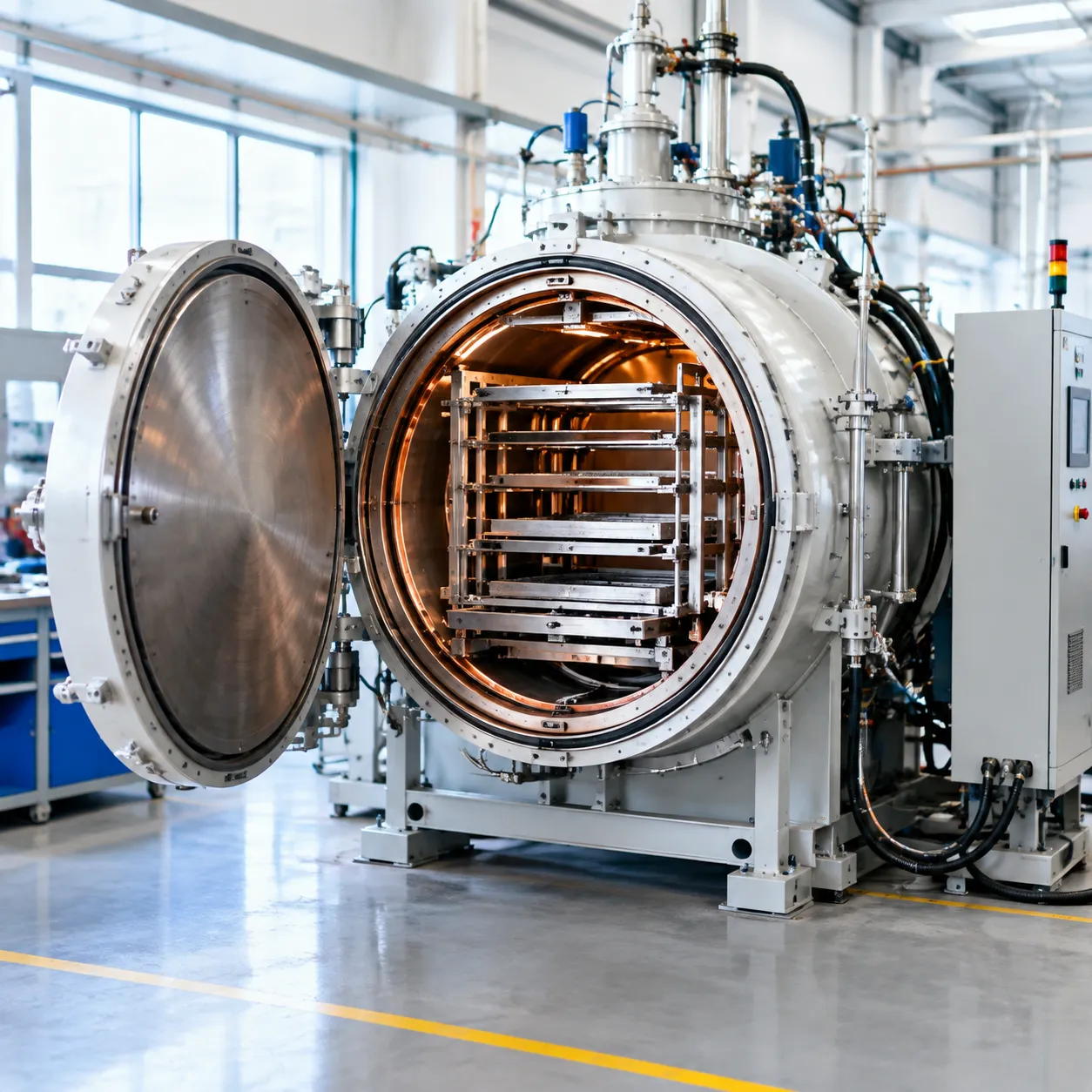
General Working Temperature Ranges by Filler-Metal Family
The active chemistry of the filler metal dictates the primary thermal window in the vacuum furnace. Below are the standard operational ranges across the most common industrial filler alloy families:
| Filler Metal Family | Standard AWS / ISO Class | Typical Vacuum Brazing Range (°C) | Typical Vacuum Brazing Range (°F) | Primary Shop Applications |
|---|---|---|---|---|
| Aluminum-Silicon | BAlSi-4, BAlSi-5 | 575°C – 605°C | 1067°F – 1121°F | Heat exchangers, aviation cooling plates |
| Silver-Based | BAg-8, BAg-24 | 680°C – 840°C | 1256°F – 1544°F | Electrical contacts, precision optics, medical |
| Copper & Copper-Nickel | BCu-1, BCuNi | 1085°C – 1120°C | 1985°F – 2048°F | Carbon steel, heavy tooling, hydraulic fittings |
| Nickel-Based | BNi-2, BNi-5, BNi-7 | 980°C – 1190°C | 1796°F – 2174°F | Aerospace turbines, EGR coolers, chemical valves |
| Active Braze Alloys (ABA) | Incusil-ABA, Cusil-ABA | 815°C – 925°C | 1499°F – 1697°F | Ceramic-to-metal seals, sapphire windows |
| Cobalt & Precious Alloys | BCo-1, BAu-4 | 1020°C – 1230°C | 1868°F – 2246°F | High-stress turbine vanes, nuclear components |
For complex hot-section components, following precise nickel brazing specifications and cycle parameters ensures that high-temperature nickel alloys wet narrow joints cleanly without leaving residual voids.
Temperature Ranges and Considerations by Base Material
Every parent alloy introduces distinct physical constraints that dictate the upper and lower limits of the furnace cycle:
-
- Austenitic Stainless Steels (304L, 316L, 321): Commonly processed between 1010°C and 1120°C (1850°F and 2048°F). We avoid prolonged holds in the chromium carbide precipitation range (425°C to 860°C / 797°F to 1580°F) by maintaining rapid transitions.
- Nickel Superalloys (Inconel 625/718, Hastelloy X): Typically brazed between 1040°C and 1180°C (1904°F and 2156°F). Processing temperatures must be tightly coordinated with downstream solution annealing and aging cycles to protect mechanical properties.
- Titanium and Ti-Alloys (Ti-6Al-4V): Strictly held between 840°C and 940°C (1544°F and 1724°F). Going above the beta-transus temperature (around 995°C / 1823°F) triggers irreversible grain coarsening and severe loss of ductility.
- Refractory Metals (Molybdenum, Tungsten): Processed at elevated levels from 1100°C up to 1350°C (2012°F to 2462°F) using specialized high-temperature vacuum equipment with pure tungsten or molybdenum hot zones.
Critical Temperature Limits and Risk Factors for Base Metals
Running outside the optimal vacuum brazing temperature range introduces severe metallurgical defects that compromise part reliability:
-
- Parent Metal Dissolution and Erosion: High furnace temperatures combined with aggressive boron- or silicon-bearing nickel alloys cause rapid base-metal attack. Thin-walled heat exchanger fins can dissolve completely if the peak temperature exceeds the liquidus by more than 30°C (54°F).
- Excessive Grain Growth: Pushing stainless steels or superalloys beyond their annealing ceilings causes rapid crystalline grain growth, drastically reducing fatigue strength and impact resistance.
- Alloy Element Volatilization: High-vacuum environments lower the boiling point of volatile alloying elements. If we run temperatures too high without partial-pressure management, elements like chromium, manganese, and zinc vaporize, causing alloy depletion and hot-zone contamination.
- Distortion and Residual Stress: Excessive peak temperatures lower the yield strength of the base metals to near zero inside the furnace, causing heavy components to sag, warp, or creep under their own weight.
How to Determine the Best Vacuum Brazing Temperature
Start with the Filler-Metal Technical Data Sheet
Every brazing alloy comes with defined thermal characteristics. We always start by reviewing the technical data sheet (TDS) for two critical figures:
-
- Solidus Temperature: The highest temperature at which the alloy remains completely solid.
- Liquidus Temperature: The lowest temperature at which the alloy is completely molten.
Vacuum brazing must occur above the liquidus to ensure total fluidity. Eutectic alloys melt at a single, distinct point, while non-eutectic alloys melt across a range (the "plastic range"). Wide plastic ranges require rapid heating past the solidus to prevent liquation—where lower-melting phases separate and leave an un-melted alloy skeleton behind.
Evaluate Base-Material Thermal and Metallurgical Properties
The peak process temperature must remain well below the solidus of the parent metals. When processing various parts across industrial vacuum furnace applications, we evaluate key material risk factors:
-
- Grain Growth: Excessive heat coarsens base-metal grains, permanently lowering tensile strength.
- Phase Transformations: Austenitic stainless steels risk carbide precipitation if held too long in sensitization zones.
- Vapor Pressure: High temperatures under deep vacuum cause elements like zinc, cadmium, or high-percentage silver to volatilize, contaminating the hot zone.
| Base Material Group | Typical Braze Temp Range | Metallurgical Boundary / Risk |
|---|---|---|
| Austenitic Stainless (304, 316) | 1010°C – 1150°C (1850°F – 2100°F) | Carbide precipitation / Intergranular corrosion |
| Precipitation Hardening Steel (17-4PH) | 1040°C – 1080°C (1904°F – 1976°F) | Solution anneal over-soaking |
| Nickel Superalloys (Inconel) | 1065°C – 1190°C (1950°F – 2175°F) | Grain boundary attack and alloy depletion |
| Titanium & Ti-Alloys | 880°C – 950°C (1616°F – 1742°F) | Beta-transus grain growth & embrittlement |
Account for Joint Clearance, Mass, and Part Geometry
Part geometry and fit-up dictate how heat and molten filler behave in the vacuum chamber:
-
- Joint Gap Size: Tight clearances (0.025 mm to 0.075 mm / 0.001 in to 0.003 in) promote strong capillary action at nominal temperatures. Wider gaps demand slightly lower temperatures with higher-viscosity fillers to prevent runoff.
- Thermal Mass Distribution: Asymmetric assemblies (thick sections joined to thin foils) experience thermal lag. The thin section reaches the furnace setpoint faster; setting the temperature too high will burn or erode the thin component before the heavy section reaches brazing heat.
Calculate and Set a Suitable Process Temperature Margin
A reliable rule of thumb is setting the peak furnace setpoint 25°C to 55°C (45°F to 100°F) above the filler metal liquidus. This temperature margin accounts for real-world production variables:
-
- Hot-Zone Radiative Losses: Radiative heat transfer in a vacuum relies on line-of-sight; a positive thermal margin ensures deep, shielded joint interiors reach complete melting temperatures.
- Surface Tension Reduction: The extra superheat lowers liquid filler surface tension, accelerating wetting and gap filling.
- Diffusion Bonding: A calibrated margin allows slight solid-solution diffusion between the filler and base metal, resulting in maximum shear strength at the joint interface.
Vacuum Brazing Furnace Cycle: Temperature Stages Explained
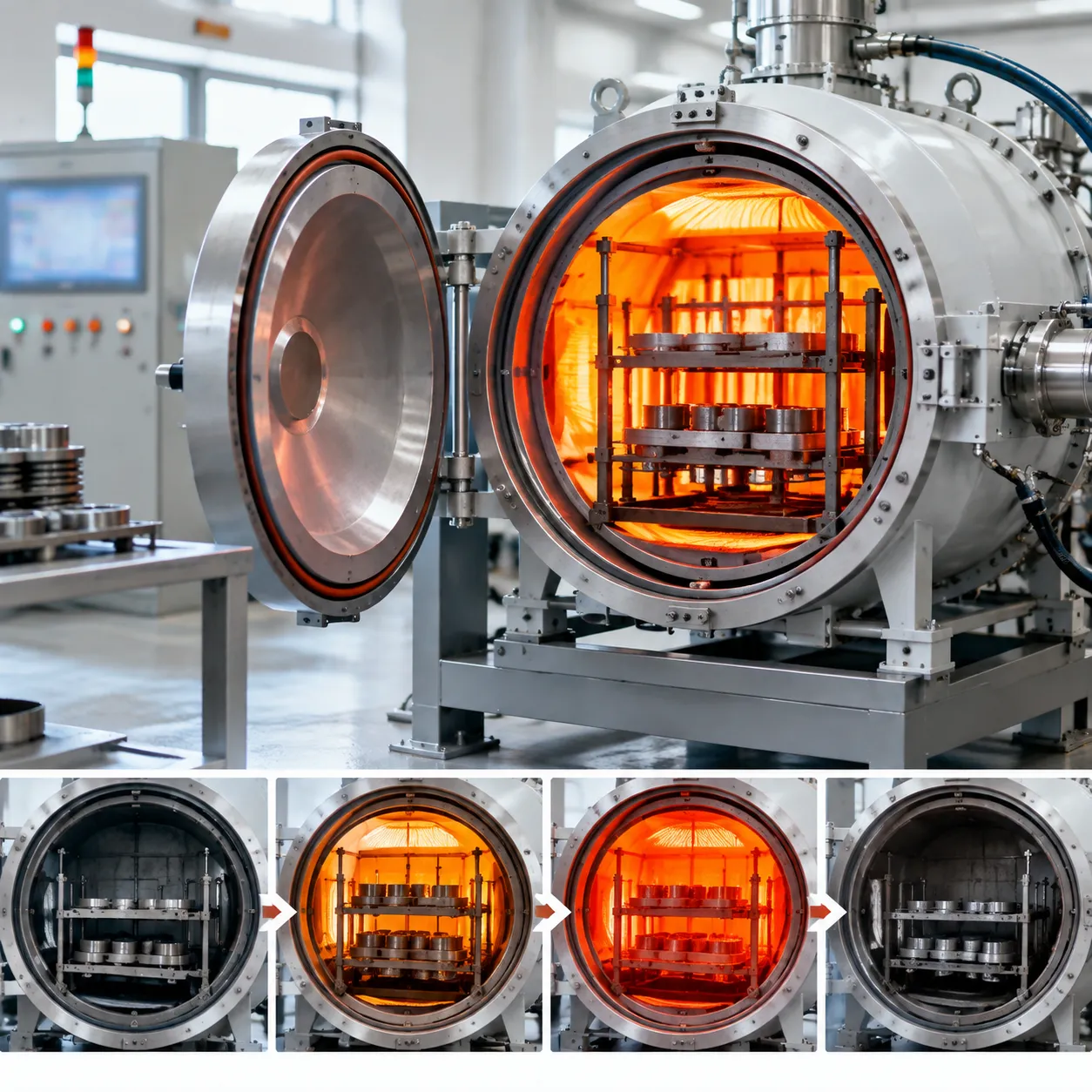
Managing your vacuum brazing furnace temperature requires breaking the entire process into distinct, manageable phases. Skipping a step or rushing a ramp can ruin parts, produce voids, or distort complex assemblies.
Temperature (°C / °F)
▲
│ [5] Peak Brazing Hold
│ (Brief Liquidus Soak)
│ ┌───────┐
│ [4] Fast Ramp │ │
│ ╱ ╲ [6] Partial-Pressure
│ [3] Intermediate ┌─┘ ╲ Gas Quench / Cool
│ Thermal Soak ╱ ╲
│ ┌───────────────┘ ╲
│ [2] Binder ╱ ╲
│ Burnout ╱ ▼
│ ┌────────────┘ Room Temp
│ ╱
│ ╱ [1] Initial Pump-Down & Slow Ramp
└───────────────────────────────────────────────────────────► Time
Loading, Cleaning, and Fixturing Preparation
Flawless brazing starts outside the hot zone:
-
- Chemical Cleaning: Remove all hydrocarbons, cutting oils, drawing compounds, and surface oxides using ultrasonic solvent degreasing or acid pickling.
- Thermal Expansion Matching: Fixture parts using low-expansion materials (like graphite, molybdenum, or specialized stainless alloys) to prevent binding or joint movement during thermal expansion.
- Paste Application: Apply filler metal alloy pastes, foils, or preforms precisely, ensuring even distribution across the joint gap.
Initial Pump-Down and Preheating Stage
Once the furnace door closes, the roughing and diffusion pumps draw the chamber down to working vacuum:
-
- Vacuum Crossover: We evacuate the chamber below 1 × 10⁻⁴ mbar before firing the heating elements to avoid oxidization.
- Soft Preheating: The initial ramp brings the load gently to 200 °C to 300 °C (392 °F to 572 °F), driving off residual surface moisture without shocking cold parts.
Controlled Slow Heating and Binder Burnout
If you use brazing paste, binder burnout is a critical stage in the vacuum furnace brazing cycle:
-
- Burnout Plateau: We program a soak between 450 °C and 550 °C (842 °F to 1022 °F).
- Volatile Evacuation: Organic binders decompose and vaporize. The vacuum pumps evacuate these off-gases before higher temperatures can bake carbon residues into the joint.
- Controlled Vacuum Brazing Atmosphere: For applications requiring specialized thermal profiles, such as a vacuum brazing furnace for aluminum coolers, keeping this stage stable prevents surface contamination and porosity.
Intermediate Soaking for Thermal Equalization
Thick and thin sections heat at vastly different rates:
-
- Equalization Plateau: We hold the furnace between 50 °C and 100 °C (90 °F to 180 °F) below the solidus temperature of the filler alloy.
- Core Stabilization: This soak ensures the center of heavy components reaches thermal equilibrium with thin external fins, preventing localized distortion and uneven melting.
| Cycle Phase | Typical Target Range | Primary Purpose |
|---|---|---|
| Binder Burnout | 450 °C - 550 °C (842 °F - 1022 °F) | Evaporate paste vehicles without leaving carbon soot |
| Equalization Soak | 50 °C - 100 °C below solidus | Eliminate thermal gradients across variable cross-sections |
| Peak Brazing | 25 °C - 50 °C above liquidus | Melt filler metal and achieve full capillary draw |
| Gas Quench | Below 400 °C (752 °F) before air release | Rapid cooling while protecting joint surfaces from oxidation |
Final Ramp to Target Brazing Temperature
Once the entire load stabilizes, we initiate a rapid ramp to the peak vacuum brazing furnace temperature:
-
- Fast Transition: Accelerating the heating rate through the alloy's melting range minimizes the risk of liquation (where lower-melting components separate from higher-melting elements).
- Target Temperature Window: The furnace setpoint is placed 25 °C to 50 °C (45 °F to 90 °F) above the filler metal's liquidus point to ensure full alloy liquidity.
Brazing Hold Time and Load Stabilization
The peak brazing hold time must be short and precise:
-
- Capillary Draw: Maintain peak temperature for 3 to 15 minutes, depending on the size of the assembly.
- Preventing Base Metal Erosion: Overextending the hold time causes the molten filler metal to aggressively alloy with and erode thin base-metal walls.
- Precision Control: At Haitem Furnace, we engineer our multi-zone heating systems to maintain tight hot zone temperature uniformity, ensuring all joints melt simultaneously.
Controlled Vacuum and Partial-Pressure Cooling Stages
Cooling is just as crucial as heating for joint integrity:
-
- Solidification Soak: The furnace cools under vacuum below the alloy's solidus point, allowing the braze fillet to solidify undisturbed.
- Partial-Pressure Inert-Gas Cooling: Once the joint is solid, high-purity inert gas (typically Nitrogen or Argon at 1 to 6 bar) is backfilled to speed up cooling. Understanding these atmosphere mechanics is one of the vacuum brazing vs. furnace brazing key differences that guarantees bright, oxidation-free parts.
- Unloading: The chamber remains sealed until load thermocouples register below 100 °C (212 °F) to avoid thermal discoloration when exposed to ambient air.
Heating Rate and Cooling Rate in Vacuum Brazing
Controlling thermal ramp speeds inside a high-temperature vacuum furnace is just as vital as hitting the final target setpoint. The speed at which an assembly heats up and cools down governs temperature uniformity across varying cross-sections, directly influencing part geometry, joint fill, and residual stress levels.
Selecting the Optimal Heating Rate for Complex Assemblies
When brazing assemblies that feature both thin sheet sections and massive solid blocks, a standard flat ramp will quickly cause thermal imbalances. We tailor the vacuum brazing heating rate based on load density, cross-sectional variance, and material conductivity:
-
- Heavy or Asymmetrical Loads: Ramp slowly at 5°C to 10°C (9°F to 18°F) per minute to prevent the outer shell of thick sections from overheating while the core lags behind.
- Uniform, Thin-Wall Components: Can handle faster heating rates of 15°C to 20°C (27°F to 36°F) per minute, shortening overall cycle times without inducing warping.
- Sub-Liquidus Approach: Once the load passes its final intermediate soak, we slow the final approach to the brazing peak down to 3°C to 5°C (5°F to 9°F) per minute so that the entire assembly reaches the target brazing temperature simultaneously.
Utilizing an advanced vacuum brazing furnace equipped with multi-zone temperature control ensures that high-mass tooling and lightweight components absorb heat at a balanced, predictable rate.
Key Cooling Rate Considerations and Thermal Stress Management
Managing the cooling rate in vacuum brazing requires a distinct two-phase strategy:
-
- Solidification Phase (Above Solidus): Cool slowly under vacuum or static inert gas until the filler metal completely freezes throughout the joint clearance. Moving parts or blasting gas during this liquid-to-solid phase causes liquation tears and fractured braze seams.
- Stress-Relief Phase (Below Solidus): Once the joint solidifies (typically 50°C to 100°C / 90°F to 180°F below the solidus point), controlled gas quenching can begin. We introduce high-purity argon or nitrogen under partial pressure to accelerate cycle times while moderating cooling gradients across mismatched alloys.
| Cooling Phase | Temperature Window | Atmosphere / Control | Primary Objective |
|---|---|---|---|
| Initial Quench Delay | Peak temp down to solidus -50°C (-90°F) | High vacuum or low static pressure | Solidify filler metal without turbulence or shear |
| Intermediate Gas Cool | Solidus down to ~400°C (752°F) | Controlled partial-pressure inert gas | Prevent thermal shock and residual stress buildup |
| Final Fast Cool | Below 400°C (752°F) down to room temp | Forced gas circulation / convection | Rapid turnaround for safe furnace unloading |
Why Rapid Thermal Ramps Cause Part Distortion and Joint Defects
Rushing thermal ramps creates sharp temperature gradients between the exterior surfaces and interior joint channels. These localized thermal variations lead to several critical production failures:
-
- Premature Alloy Melting and Runoff: If thin sections reach the filler metal liquidus before heavy mating parts get up to temperature, the molten alloy flows toward the hot thin zone and away from the cold joint gap, leaving voids behind.
- Permanent Part Warping: Rapid heating forces uneven thermal expansion across thin-to-thick transitions, permanently warping precision-machined tolerances.
- Braze Joint Microcracking: Excessively fast cooling locks severe residual tensile stresses into the joint seam, leading to immediate boundary cracking or delayed stress failures under working loads.
Vacuum Level and Atmosphere Control
Why Vacuum Quality Directly Affects Wetting and Bonding
In vacuum brazing, we eliminate chemical fluxes entirely. Instead, the furnace environment itself acts as the cleaning agent.
-
- Oxide Dissociation: Under high vacuum, residual oxygen and water vapor drop to trace levels. At elevated temperatures, surface oxide films break down thermodynamically, exposing clean, active base metal.
- Capillary Pull: Clean metallic surfaces lower the interfacial energy, allowing molten filler metal to spread effortlessly into narrow joint gaps through pure capillary action.
- Degassing the Molten Pool: Vacuum drawing extracts entrapped gases from the joint clearance, preventing microscopic gas pockets, voids, and leak paths.
Vacuum Level Requirements Across Different Alloys and Base Metals
Different materials demand specific vacuum operating ranges to prevent oxidation while maintaining chemical stability.
| Base Metal / Filler Alloy | Typical Vacuum Level (mbar) | Typical Vacuum Level (Torr) | Temperature Window (°C / °F) | Atmosphere Consideration |
|---|---|---|---|---|
| Stainless Steel / Ni-Based Alloy | 10⁻⁴ to 10⁻⁵ | 10⁻⁴ to 10⁻⁵ | 1000°C–1200°C (1832°F–2192°F) | High vacuum to break chromium oxides |
| Titanium & Refractory Alloys | < 10⁻⁵ | < 10⁻⁵ | 850°C–1050°C (1562°F–1922°F) | Ultra-high vacuum; zero active gas |
| Copper & Mild Steel / Ag-Based | 10⁻³ to 10⁻⁴ | 10⁻³ to 10⁻⁴ | 650°C–850°C (1202°F–1562°F) | Medium vacuum is sufficient |
| Alloys Containing Volatiles (Cr, Mn) | 0.5 to 5 (Partial Pressure) | 0.38 to 3.8 | Process-dependent | Controlled inert gas blanket |
Balancing Vacuum Depth with High-Temperature Furnace Settings
Deeper vacuum is not always better. When you push your vacuum brazing furnace temperature above 900°C (1652°F) under an aggressive high vacuum (10⁻⁵ mbar), elements with high vapor pressures—such as manganese, chromium, and silver—can boil off.
This element vaporization leads to three major problems:
1. Alloy Depletion: The filler metal loses volatile elements, shifting its solidus-liquidus chemistry and weakening joint strength.
2. Hot-Zone Deposition: Metallic vapors condense on ceramic insulators, heating elements, and radiation shields, creating short circuits and reducing equipment life.
3. Porous Joints: Boiling within the braze gap leaves permanent micro-voids.
To prevent vaporization, we introduce high-purity argon or nitrogen partial pressure (typically 0.5 to 5 mbar) right before the alloy reaches its melting point. This inert gas blanket suppresses vapor formation while maintaining a clean, flux-free joint area.
Partial-Pressure Inert Gas Cooling for Joint Protection
Once filler metal solidifies, rapid, controlled cooling prevents undesirable phase transformations, excessive grain growth, and cycle bottlenecks.
Using a specialized single-chamber vacuum furnace with high-pressure gas quenching, we backfill the chamber with high-purity argon or nitrogen (typically 2 to 10 bar or higher). This forced-convection gas stream cools the assembly quickly past critical embrittlement zones while keeping every surface bright, clean, and oxidation-free.
For high-throughput industrial operations, running a gas quench vacuum furnace ensures the entire workload drops uniformly below oxidation threshold temperatures before the chamber opens to ambient air.
Temperature Uniformity Inside the Furnace Hot Zone
Hot-zone thermal consistency is often the deciding factor between a fully bonded assembly and a batch of scrapped parts. If one corner of the hot zone lags behind, the filler alloy will not melt, while an overheated zone risks base metal erosion. Achieving a tight vacuum brazing furnace temperature tolerance across the entire working volume ensures identical joint strength and flow behavior on every single part.
Why Hot-Zone Temperature Uniformity Dictates Joint Quality
Brazing relies on narrow process windows—often just ±5 °C (±9 °F) to ±10 °C (±18 °F) around the working point. Poor hot zone temperature uniformity creates two simultaneous failure modes in a single load:
-
- Cold spots: The braze alloy stays below its liquidus point, causing incomplete capillary fill, large voids, and low joint shear strength.
- Hot spots: Excessive localized heat triggers base-metal dissolution, alloy runoff, intergranular attack, and excessive part distortion.
- Non-simultaneous melting: Multi-joint assemblies warp as one side melts and solidifies earlier than the other, introducing severe residual stress.
Hot-Zone Uniformity Risks
Cold Spot: < Liquidus → Incomplete Joint Fill
Target Window: ±5°C / ±9°F → 100% Capillary Penetration
Hot Spot: > Limit → Base Metal Erosion / Warping
Essential Furnace Design Specifications to Evaluate
When evaluating a high-temperature vacuum furnace for brazing duties, specific mechanical and electrical configurations determine how evenly heat distributes:
| Feature | Key Consideration | Impact on Uniformity |
|---|---|---|
| Heating Element Layout | 360-degree radial coverage vs. multi-zone trim elements | Eliminates directional shadowing and cold corners. |
| Hot Zone Insulation | Multi-layer all-metal shields (Molybdenum/SS) vs. graphite felt | Metal shields offer cleaner vacuum; graphite felt retains heat more uniformly at ultra-high temps. |
| Control Zones | Independent multi-zone PID temperature control | Automatically balances power output across front, middle, and rear sections. |
| Nozzle Penetrations | Gas quench nozzle distribution | Poorly sealed cooling ports can create persistent localized cold spots during heating. |
Conducting Temperature Uniformity Surveys (TUS) and Calibration
Periodic qualification is mandatory to verify that the furnace meets standard industrial criteria (such as AMS 2750 or CQI-9). A comprehensive furnace temperature uniformity survey maps the exact thermal profile of your usable workspace:
-
- Sensor Placement: We mount a multi-point thermocouple array across the corners, center, and edges of the hot zone basket.
- Multi-Step Testing: The survey runs through actual operating setpoints—typically preheat ranges (e.g., 550 °C / 1022 °F, 850 °C / 1562 °F) and peak brazing ranges (1050 °C to 1200 °C / 1922 °F to 2192 °F).
- Offset Adjustments: Individual zone trim values are calibrated in the controller to balance thermal variations back within acceptable Class 2 (±6 °C / ±10 °F) or Class 1 (±3 °C / ±5 °F) limits.
Following a rigorous vacuum furnace calibration guide protects against drift over extended production campaigns and ensures complete compliance with aerospace and medical brazing standards.
Understanding Furnace Setpoint vs. Actual Load Temperature
Relying solely on control thermocouples located near the heating elements leads to premature cycle transitions. In a vacuum, heat transfers almost exclusively through radiation, creating an inherent lag between the element and the core of the workpiece.
-
- Control Thermocouples: Read the radiant temperature near the heating elements and reach the target setpoint quickly.
- Load Thermocouples: Attached directly to the thickest sections of the actual parts to measure true core temperature.
- Thermal Soak Rule: We never initiate the final brazing hold timer until every load thermocouple reaches the designated vacuum furnace temperature control band.
Common Vacuum Brazing Temperature Problems and Troubleshooting
When parts come out of the furnace with defective joints, improper thermal management is usually the culprit. Dialing in the correct vacuum brazing furnace temperature requires balancing thermal soak times, alloy chemistry, and vacuum integrity. Here is how we troubleshoot and resolve the most frequent vacuum brazing issues on the shop floor.
Troubleshooting Filler Metal That Does Not Melt
If the braze alloy remains in its original paste, foil, or wire form after a completed cycle, the actual load temperature failed to reach the alloy's melting range.
-
- Lagging Core Temperatures: The furnace control thermocouple may indicate that the chamber reached target heat, but dense or shielded parts often lag behind. Increasing the stabilization soak time resolves this.
- Thermocouple Drift or Misplacement: Control thermocouples degrade over time. Calibrate your sensors and place load thermocouples directly at the heaviest section of the assembly.
- Underestimated Liquidus: Ensure your peak setpoint sits 25 °C to 55 °C (45 °F to 100 °F) above the true liquidus point of the specific filler alloy batch.
Resolving Filler Metal Melting Without Capillary Flow
When the alloy melts into a ball instead of flowing into the joint gap, surface wetting has failed.
-
- Surface Oxide Formation: Certain elements like aluminum, titanium, or chromium form tenacious surface oxides if the vacuum level is too low. Maintain a deeper vacuum or utilize a partial-pressure reducing gas during heating.
- Insufficient Pre-Braze Cleaning: Residual machining oils and fingerprints carbonize under heat, creating an impenetrable barrier. Solvent degreasing and ultrasonic cleaning prior to loading are mandatory.
- Improper Joint Clearance: If the gap exceeds 0.10 mm (0.004 in) for high-temperature nickel or copper alloys, filler metal capillary flow drops significantly. Re-machine or clamp joints to maintain tight tolerances (typically 0.025 mm to 0.05 mm / 0.001 to 0.002 in).
Preventing Excessive Filler Spreading, Erosion, and Base Metal Attack
Aggressive metallurgical interaction can thin thin-walled sections or cause alloy runoff across non-joint areas.
-
- Excessive Peak Temperature: Operating too far above the alloy liquidus increases chemical reactivity. Lower your target brazing temperature closer to the working minimum.
- Overextended Hold Times: Holding at peak temperature for too long allows active elements (such as boron or silicon in nickel alloys) to dissolve the base metal. Cut your peak dwell time down to 5–10 minutes once temperature uniformity is achieved.
- Using Braze Stop-Off: Apply ceramic-based stop-off coatings around the joint perimeter to mechanically block molten filler migration.
Eliminating Joint Voids, Gas Entrapment, and Incomplete Fill
Internal voids weaken structural integrity and cause pressure-test failures.
| Cause | Mechanism | Solution |
|---|---|---|
| Volatile Binder Outgassing | Binder in braze pastes boils violently during the ramp | Insert an intermediate thermal soak at 450 °C to 550 °C (842 °F to 1022 °F) to burn off organics slowly. |
| Uneven Gap Expansion | Dissimilar metals expand at different rates, pinching gaps | Recalculate joint clearances based on thermal expansion coefficients (CTE) at peak temperature. |
| Alloy Liquation | Slow heating through the solidus-liquidus range causes low-melt components to separate | Increase the ramp rate through the melting range once thermal equilibrium is reached. |
Minimizing Post-Braze Warping and Dimensional Distortion
Assemblies with tight geometric tolerances require controlled heating and cooling curves to prevent internal stress build-up.
-
- Ramping Too Quickly: Rapid heating induces severe thermal gradients between thin edges and thick sections. We recommend staged heating ramps with isothermal equalization stops.
- Aggressive Gas Quenching: High-pressure gas quenching right at the solidus point shocks the metal lattice. Delay rapid gas cooling until the load drops safely below 500 °C (932 °F).
- Fixturing Restraint: Over-constraining assemblies with rigid fixtures causes buckling as parts expand. Use low-mass, thermally matched molybdenum or graphite fixtures.
Addressing Joint Discoloration and Vacuum Surface Contamination
Bright, clean parts are the hallmark of a healthy vacuum process. Discoloration indicates gas interaction at elevated temperatures.
-
- Micro-Leaks in the Chamber: Check seals, feedthroughs, and valves with a helium mass spectrometer leak detector. Gaining a solid understanding of how a vacuum furnace works helps isolate mechanical seal issues before running high-value production loads.
- Hot Unloading: Opening the furnace door while the load is above 150 °C (302 °F) causes immediate atmospheric oxidation, turning stainless steels and nickel alloys yellow, blue, or purple.
- Contaminated Quench Gas: Ensure high-purity inert backfill gas (Argon or Nitrogen with 99.999% purity) to keep components completely scale-free throughout the cooling phase.
How to Validate a Vacuum Brazing Temperature Cycle
Dialing in the correct vacuum brazing furnace temperature is never a matter of guesswork. Before releasing a new part geometry or filler metal to high-volume production, we run a rigorous thermal validation protocol to ensure joint integrity, repeatable capillary flow, and zero component distortion.
Running Test Assemblies and Load Qualification Trials
We never rely solely on empty-chamber runs to qualify a cycle. Real production loads alter furnace thermodynamics, which makes running instrumented test assemblies essential:
-
- Dummy-Load Thermal Profiling: We load the hot zone with representative scrap or dummy parts matching the thermal mass of the actual production batch.
- Trailing Load Thermocouples (TCs): We attach calibrated Type R or Type S thermocouples directly to the joint interfaces of the thickest and thinnest parts in the load.
- Thermal Lag Mapping: Monitoring load TCs against the furnace control sensors reveals the exact lag time required for the entire charge to equalize at each intermediate soak.
Non-Destructive and Destructive Joint Inspection Methods
Validating the cycle requires verifying both surface wetting and subsurface bonding. We combine non-destructive testing (NDT) with destructive metallurgical evaluations to verify joint quality:
| Inspection Category | Test Method | Defect Checked |
|---|---|---|
| Non-Destructive | Visual & Optical Inspection (10x–50x) | Fillet continuity, surface discoloration, excessive alloy runoff |
| Non-Destructive | Helium Mass Spectrometer Leak Testing | Micro-porosity and through-joint vacuum/pressure leaks |
| Non-Destructive | Radiographic (X-ray) / Ultrasonic Testing | Internal voids, incomplete penetration, fluxless bridging gaps |
| Destructive | Metallographic Cross-Sectioning | Intermetallic phase formation, base metal erosion, fillet geometry |
| Destructive | Tensile / Shear / Peel Testing | Mechanical joint strength vs. base metal yield strength |
Data Logging Critical Thermal, Vacuum, and Timing Parameters
A validated cycle relies on synchronized process data. High-accuracy multi-channel recorders track the interaction between temperature ramps, furnace atmosphere, and vacuum recovery:
-
- Load vs. Control Delta: We record the exact moment all part thermocouples cross the filler alloy solidus and liquidus points. Understanding radiation-driven heat transfer in a vacuum furnace helps explain why core sections lag behind surface heating.
- Vacuum Level at Liquidus: We ensure furnace chamber pressure remains well below 1 × 10⁻⁴ mbar before ramping to the peak brazing temperature to avoid oxidation.
- Hold Time Precision: We track the exact minutes spent at the target peak temperature to prevent over-erosion of thin base metal walls.
Establishing a Qualified, Repeatable Production Process Window
Once test assemblies pass all structural and metallurgical checks, we define the acceptable operating window for continuous production:
-
- Set Upper and Lower Temperature Limits: Establish tight setpoint boundaries (typically ± 5 °C / ± 9 °F) around the validated target.
- Define Minimum and Maximum Load Weights: Lock the permissible batch mass range so heating and cooling lag times stay within validated limits.
- Standardize Fixturing and Placement: Document exact part spacing, rack layouts, and filler-metal placement in standard operating procedures (SOPs) to guarantee batch-to-batch repeatability.
Selecting a Vacuum Brazing Furnace for Precise Temperature Control
Key Performance Features and Heating Element Layouts
The layout of the heating elements directly dictates heat transfer efficiency and thermal balance across the entire workload. In a modern high-temperature vacuum furnace, multi-zone element configurations allow independent power adjustment across different sections of the hot zone.
| Element / Shielding Type | Typical Operating Range | Key Advantages | Best Suited For |
|---|---|---|---|
| Molybdenum / All-Metal | Up to 1,315°C / 2,400°F | Cleanest vacuum, zero carbon contamination | Aerospace, medical, stainless steels, superalloys |
| Graphite Elements & Felt | Up to 1,300°C+ / 2,372°F+ | Cost-effective, robust, fast thermal response | Industrial assemblies, copper/nickel-brazed steels |
| Multi-Zone Trim Elements | Process specific | Eliminates edge heat losses and cold corners | Dense batch loads, long tubular parts |
Circular, 360-degree radial element configurations eliminate thermal shadowing, ensuring heat radiates evenly from all sides into the core of the assembly.
Matching Furnace Capacity and Hot-Zone Sizing to Production Needs
Sizing a hot zone requires balancing batch volume with thermal control:
-
- Load-to-Volume Ratio: A hot zone packed past 70% usable volume often suffers from edge-to-center thermal lag. We maintain sufficient clearance between the heating elements and the part perimeter for uniform radiative transfer.
- Thermal Mass Distribution: Heavy fixtures act as heat sinks. Choosing a chamber size that accommodates low-mass fixtures prevents extended soak times and excessive cycle durations.
- Pumping Capacity Balance: Larger hot zones require matched diffusion or turbomolecular pumping systems to maintain deep vacuum levels while ramping through outgassing zones.
Why Temperature Uniformity Matters More Than Maximum Rated Temperature
A furnace capable of reaching 1,400°C (2,552°F) is ineffective for brazing if it operates with a ±15°C (±27°F) gradient across the hearth.
Most active brazing windows are narrow—often within a tight band of ±5°C (±9°F). If the front of the chamber runs hotter than the rear:
The hotter section risks filler metal over-erosion and base metal grain growth.
The cooler section fails to reach the alloy liquidus, causing incomplete capillary draw and joint voids.
Tight hot zone temperature uniformity (such as AMS 2750 Class 2, holding ±5°C / ±10°F or better) ensures every joint in the batch hits the target working window simultaneously, regardless of position on the grid.
Configuring Custom Thermal Solutions with Haitem Furnace
Standard off-the-shelf equipment does not always match demanding thermal profiles. We engineer custom vacuum furnace solutions tailored to exact production parameters, part geometries, and metallurgical requirements.
At Haitem Furnace, our focus centers on precision:
Precision Multi-Zone Control: Multi-point PID loop programming to maintain strict thermal uniformity across complex, non-uniform loads.
Application-Specific Hot Zones: Custom configurations utilizing all-metal molybdenum or high-purity graphite hot zones to match purity and budget requirements.
Integrated Gas Quench Systems: 2-bar to 10-bar directional gas cooling systems to lock in joint integrity and shorten cycle turnaround safely.
Survey-Ready Compliance: Built-in thermocouple ports and intuitive software designed for straightforward Temperature Uniformity Surveys (TUS) and process logging.
Practical Temperature-Setting Checklist for Operators
Pre-Braze Material, Alloy, and Clearance Verification
Before loading components into the hot zone, verify all physical and chemical parameters against the job routing sheet:
-
- Base Metal & Filler Compatibility: Confirm base metals and braze filler metal (paste, foil, or wire) match engineering specifications, particularly when working with specialized alloys and advanced materials.
- Joint Clearance Check: Verify that room-temperature clearances fall within the specified range (typically 0.025 mm to 0.075 mm / 0.001 in to 0.003 in). Remember to account for thermal expansion differentials between dissimilar metals.
- Surface Cleanliness: Ensure all mating surfaces are degreased, deoxidized, and dry. Residual hydrocarbons or oxides ruin capillary flow at braze temperatures.
- Filler Placement and Staging: Inspect braze alloy positioning to ensure proper contact and prevent migration away from the joint interface.
- Thermocouple Placement: Position load thermocouples in the thickest section (slowest to heat) and the thinnest section (fastest to heat) of the workload to track real-time thermal gradients.
Furnace Programming, Heating Ramp, and Soaking Checklist
Program the vacuum furnace brazing cycle to balance thermal equilibrium with minimal cycle time:
| Cycle Stage | Target Parameter / Action | Key Purpose |
|---|---|---|
| Initial Pump-Down | Reach crossover pressure (< 1 × 10⁻³ mbar / < 7.5 × 10⁻⁴ Torr) | Remove atmospheric oxygen and moisture before applying heat |
| Outgassing Soak | 400--500 °C (750--930 °F) | Allow complete binder burnout and surface outgassing without fouling the hot zone |
| Thermal Equalization Soak | 30--50 °C (55--90 °F) below solidus | Eliminate temperature deltas across thick and thin cross-sections |
| Final Braze Ramp | Rapid ramp: 10--15 °C/min (18--27 °F/min) | Minimize time in the liquation range to avoid filler separation |
| Brazing Hold / Dwell | 25--50 °C (45--90 °F) above liquidus for 5–15 minutes | Enable full capillary fill while preventing base-metal erosion |
-
- Atmosphere Control: If processing volatile elements (such as silver, copper, or manganese), verify partial-pressure inert gas injection (high-purity argon or nitrogen) is active before reaching the vapor-pressure threshold.
- Hot-Zone Uniformity Monitoring: Ensure the furnace maintains tight hot zone temperature uniformity (within ± 5 °C / ± 10 °F) across all load zones before initiating the final brazing hold.
Post-Cycle Cooling, Inspection, and Parameter Documentation
Managing the cooling rate in vacuum brazing is just as critical as the heating cycle for metallurgical integrity and dimensional stability:
-
- Solidification Dwell: Allow the workload to vacuum-cool or slow-cool below the filler solidus temperature before applying high-pressure gas quenching. Quenching above the solidus causes joint tearing.
- Controlled Gas Quench: Introduce inert gas cooling below the critical metallurgical transformation range to minimize residual stress and distortion on complex geometries.
- Unload Temperature: Do not open the chamber until the load reaches < 100 °C (< 212 °F) to prevent atmospheric surface oxidation and discoloration.
- Visual and NDT Inspection: Check joint fillets for complete, 360-degree continuous meniscus coverage, zero pinholes, and clean metallic luster. Conduct leak checks or ultrasonic inspection per quality standards.
- Data Logging: Archive thermal datalogger profiles, peak vacuum levels, partial-pressure values, and hold durations against the batch ID for full traceability and future cycle optimization.
Frequently Asked Questions About Vacuum Brazing Temperature
What temperature is commonly used for vacuum brazing?
Vacuum brazing furnace temperature spans a broad range depending on the filler alloy and base metals being joined. Most industrial applications run between 580°C and 1200°C (1076°F and 2192°F):
| Alloy Family | Typical Working Temperature Range | Common Base Metals |
|---|---|---|
| Aluminum-Silicon | 580°C – 620°C (1076°F – 1148°F) | Aluminum alloys (3003, 6061) |
| Silver-Based (Ag) | 650°C – 900°C (1202°F – 1652°F) | Copper, brass, carbon steel |
| Copper-Based (Cu) | 1085°C – 1120°C (1985°F – 2048°F) | Steels, stainless steels |
| Nickel-Based (Ni) | 1000°C – 1200°C (1832°F – 2192°F) | Stainless steel, superalloys, Inconel |
| Active/Titanium | 850°C – 1050°C (1562°F – 1922°F) | Titanium, ceramics, graphite |
Is vacuum brazing performed above the melting point of the base metal?
No. Vacuum brazing relies on melting only the filler metal while keeping the base components entirely solid. The peak process temperature must always stay comfortably below the solidus temperature (initial melting point) of the base materials to prevent part distortion, grain boundary melting, or joint collapse.
How far above the filler alloy liquidus should the furnace be set?
As a rule of thumb, we set the target vacuum brazing temperature 25°C to 55°C (45°F to 100°F) above the liquidus of the filler alloy. This process margin guarantees full liquefaction, reduces molten surface tension, and drives reliable capillary flow across tight joint clearances.
Can stainless steel be vacuum brazed successfully?
Yes. Stainless steels (300 and 400 series) are routinely vacuum brazed using nickel-based (BNi series) or pure copper filler metals. Running standard vacuum furnaces at vacuum levels around 10⁻⁴ mbar thermally breaks down tenacious chromium surface oxides ($Cr_2O_3$) at temperatures between 1020°C and 1180°C (1868°F and 2156°F), ensuring clean wetting without external fluxes.
What happens to the assembly if the brazing temperature is too high?
Excessive brazing temperatures lead to severe metallurgical and dimensional defects:
Base metal erosion: The molten filler dissolves and thins the base metal walls.
Grain coarsening: Overheating degrades parent metal tensile strength and fatigue life.
Alloy volatilization: Volatile elements (such as manganese, silver, or zinc) boil off into the furnace chamber.
Excessive run-off: Filler metal flows out of the joint, leaving voids and messy fillets.
Does a higher vacuum level always produce better brazing results?
Not necessarily. While high vacuum ($10^{-4}$ to 10⁻⁵ mbar) is ideal for stainless steels, superalloys, and refractory metals, alloys containing elements with high vapor pressures (such as silver, zinc, or manganese) will boil off at high temperatures under deep vacuum. In those cycles, introducing a partial-pressure inert gas (argon or nitrogen) at 1 to 5 mbar prevents element evaporation while maintaining a clean, oxide-free atmosphere. For step-by-step cycle profiles, consult our vacuum furnace guide.
How long should the load remain at peak brazing temperature?
The dwell time at the peak brazing temperature is kept deliberately brief—typically 5 to 20 minutes. The goal is to allow the filler metal to melt, wet, and pull completely into the joint through capillary action without soaking long enough to trigger base-metal erosion or excessive intermetallic diffusion.
Why is hot-zone temperature uniformity so critical in vacuum brazing?
Because filler alloys melt within narrow thermal bands, loose hot-zone uniformity leads to split results:
Hotter zones overheat, causing base metal erosion and braze alloy runout.
Cooler zones fail to reach liquidus, resulting in un-melted filler, cold joints, and leak paths.
Maintaining tight temperature uniformity (typically ± 5 °C / ± 10 °F) ensures identical joint quality across every part in the production batch.
Can vacuum brazing completely replace the need for flux?
Yes. In vacuum brazing, the low-oxygen, high-temperature environment acts as the cleaning agent by reducing surface oxides. This eliminates the need for chemical fluxes entirely, leaving finished assemblies clean, bright, oxide-free, and free of corrosive post-braze residues.
What is the difference between vacuum brazing and vacuum heat treatment?
-
- Vacuum Brazing: Focused on joining two or more components using a molten filler metal at a defined working temperature, followed by controlled cooling.
- Vacuum Heat Treatment: Focused on altering the microstructural and mechanical properties (such as hardness, ductility, and stress relief) of a single metal component without melting any joining alloy.
Many advanced cycles combine both steps into a single furnace run by brazing at high temperature and step-quenching into hardening or tempering ranges.