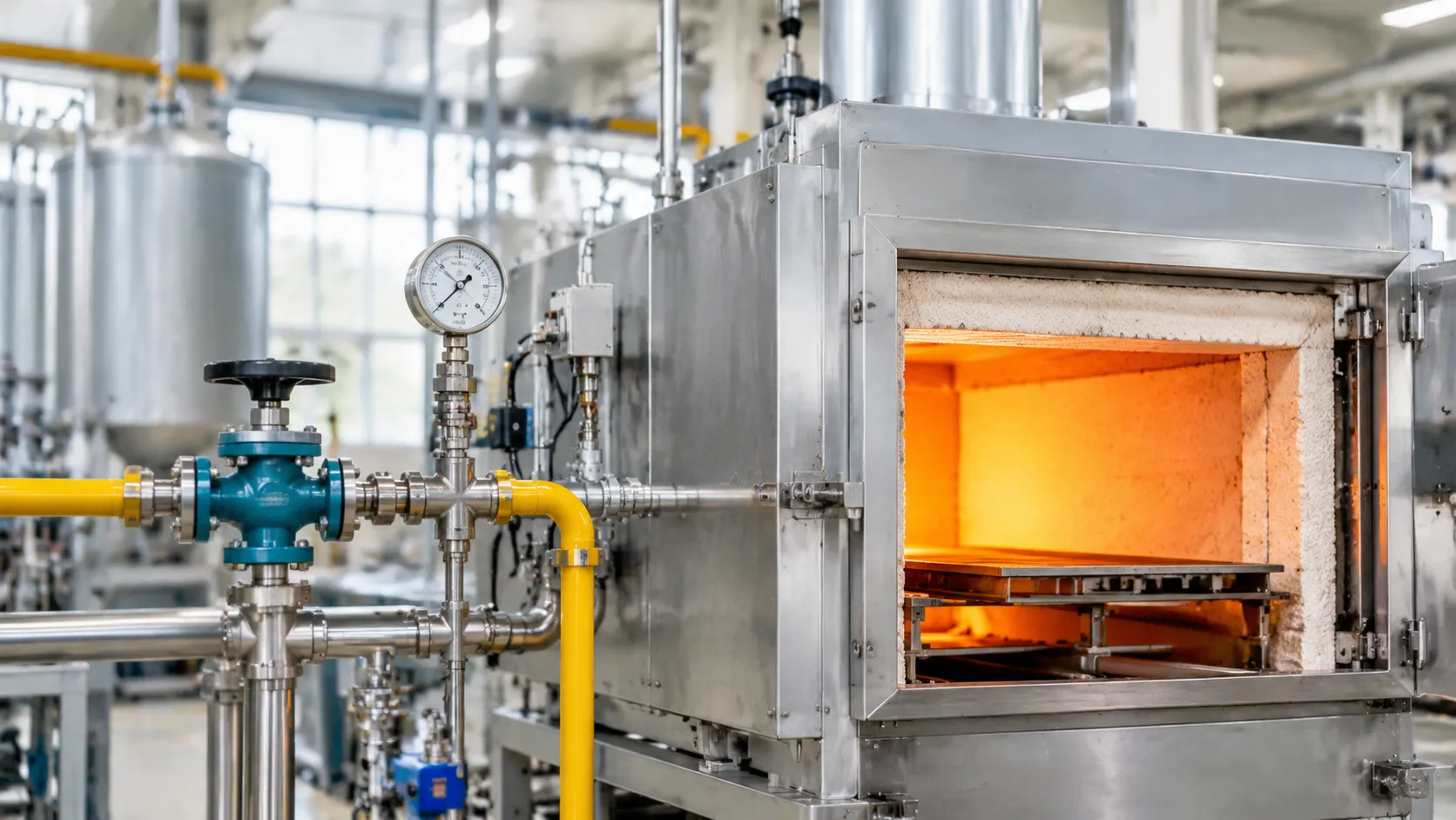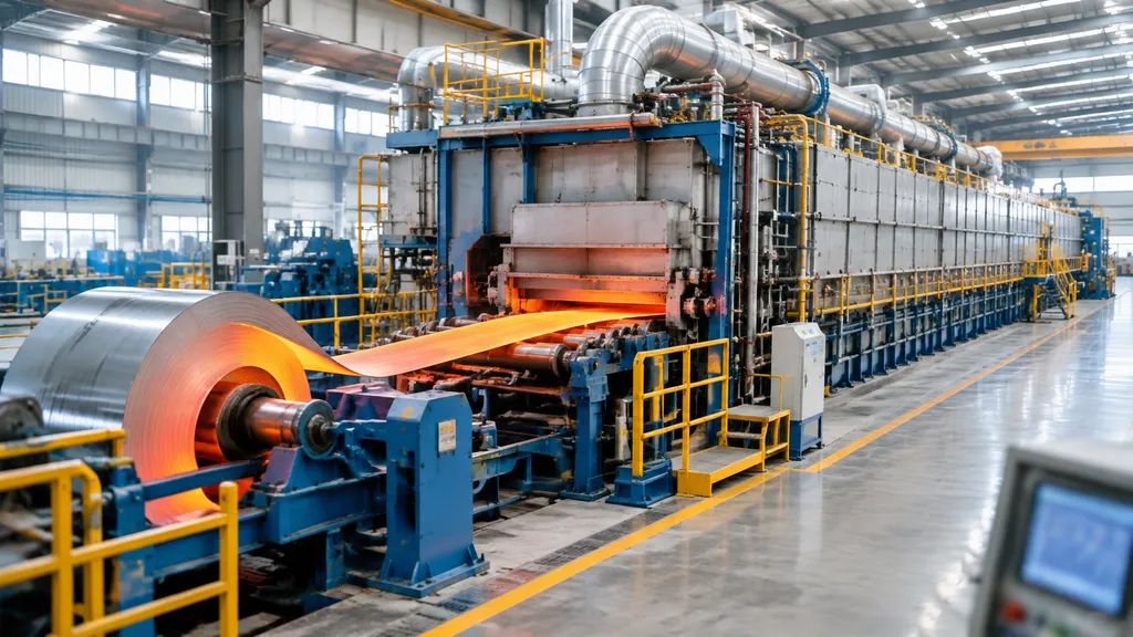
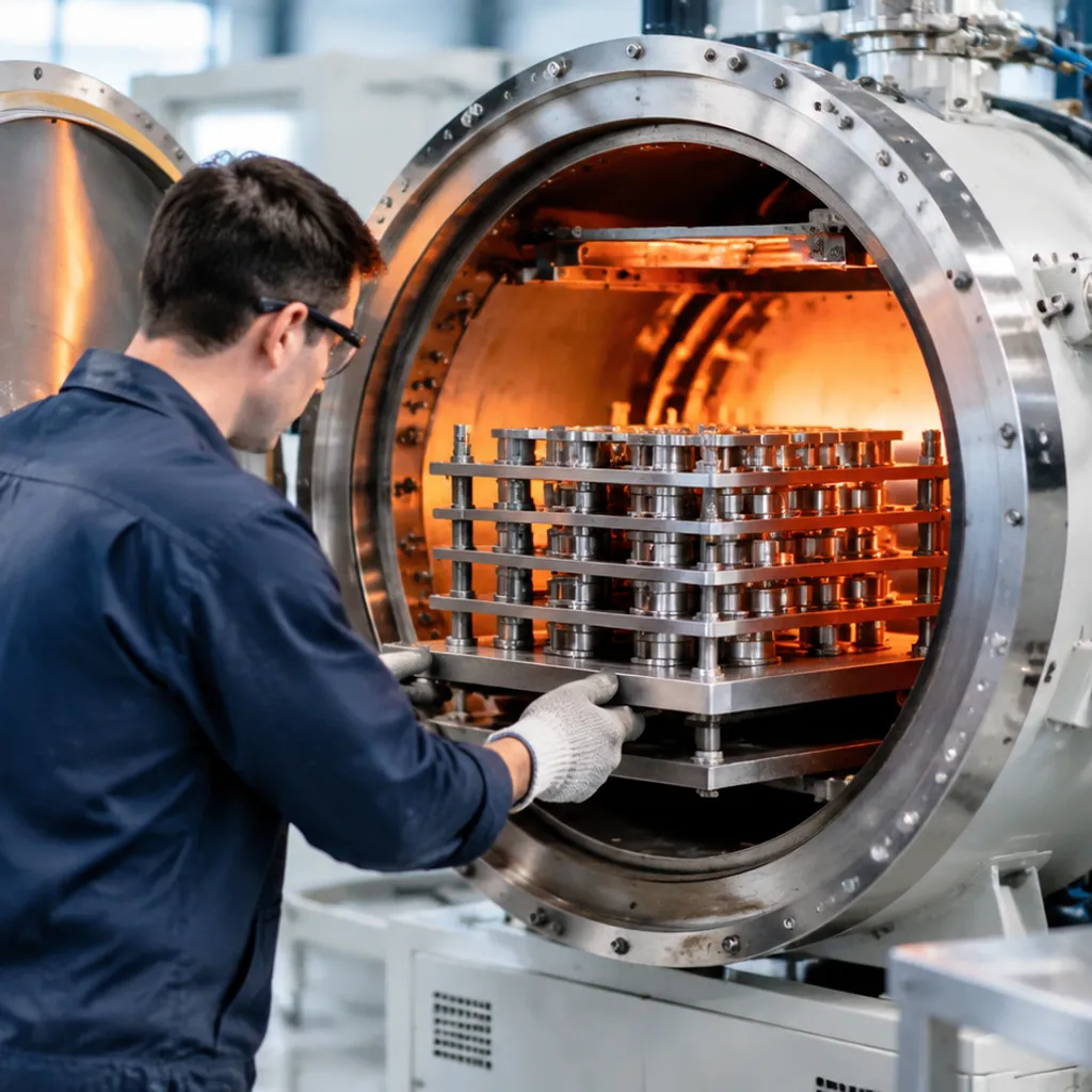
Are you struggling with oxidation, flux residue, or weak joints in your metal assemblies?
That’s where mastering the vacuum furnace brazing process changes the game.
By eliminating atmospheric contamination, this method creates ultra-clean, high-strength bonds that traditional joining techniques simply can't match. Whether you're manufacturing for aerospace, medical, or high-performance automotive applications, precision is non-negotiable.
In this guide, you’ll learn the exact step-by-step procedure, critical temperature controls, and proven best practices to achieve flawless, repeatable results every single time.
Let’s dive right in.
What Is the Vacuum Furnace Brazing Process?
If you have ever dealt with leaky joints, oxide scale, or warped assemblies after a brazing run, you know the frustration of traditional joining methods. The vacuum furnace brazing process eliminates these headaches by bonding metal parts in a completely clean, oxygen-free thermal environment.
We heat entire assemblies inside an evacuated chamber, melting a filler metal with a lower melting point than the base metals. Capillary action draws the liquid filler metal through tight joint clearances, producing exceptionally strong, hermetically sealed seams across hundreds of joints simultaneously.
Core Principles of Vacuum Brazing
The entire operation relies on precise vacuum physics and high-temperature thermal processing:
-
- Oxygen Depletion: Running processes at high vacuum levels—typically ranging from 10⁻² Pa down to 10⁻⁵ Pa—prevents base metals from oxidizing at elevated temperatures.
- Oxide Dissociation: Under deep vacuum and temperatures above 450°C (often reaching up to 1200°C or higher depending on the alloy), existing surface oxides break down naturally.
- Capillary Pull: Molten braze filler flows effortlessly into micro-gaps without surface resistance.
- Even Heat Distribution: Multi-zone temperature controls ensure the entire workload heats uniformly, minimizing internal stress.
Why Fluxless Joining Creates Cleaner Joints
Traditional brazing requires chemical flux to strip surface oxides. Flux is messy, corrosive, and notoriously difficult to remove from internal passages.
In a fluxless brazing process, the vacuum atmosphere itself acts as the cleaning agent:
-
- Zero Post-Braze Cleanup: No acid pickling, ultrasonic baths, or mechanical wire brushing are required after cycles.
- No Trapped Inclusions: Flux residues will not get trapped inside the joint interface, preventing internal voids and pinhole leaks.
- Pristine Surface Finish: Components exit the chamber bright, clean, and ready for immediate downstream machining or assembly.
- Corrosion Resistance: Eliminating chemical flux prevents premature joint failure caused by residual acids eating into the metal matrix over time.
Vacuum vs. Torch vs. Continuous Belt Brazing
| Brazing Method | Atmosphere Control | Joint Cleanliness | Distortion Risk | Ideal Production Fit |
|---|---|---|---|---|
| Vacuum Furnace | High vacuum (10⁻² to 10⁻⁵ Pa) | Maximum (Pristine, fluxless) | Lowest (Uniform heating & cooling) | Complex assemblies, high-value alloys, multi-joint parts |
| Manual Torch | Open atmospheric air | Poor (Heavy flux residue & oxide scale) | High (Localized, uneven heating) | Low-volume repair work, simple pipe fittings |
| Continuous Belt | Reducing gas (Hydrogen / Exothermic) | Moderate to Good (Fluxless for select alloys) | Moderate (Thermal gradients across belt) | High-volume, simple stamped parts, lower-temp alloys |
Main Industries Relying on Vacuum Brazing
Because this process creates leak-tight, high-integrity metallurgical bonds, several demanding sectors consider it non-negotiable:
-
- Aerospace & Aviation: Fuel manifolds, turbine components, and structural honeycombs using nickel superalloys and titanium.
- Thermal Management: Compact plate-fin heat exchangers, cold plates, and liquid cooling blocks requiring hundreds of leak-free joints in a single footprint.
- Medical Equipment: Surgical instruments and implant components requiring biocompatible, ultra-clean finishes without chemical residues.
- Power Electronics & Energy: Semiconductor baseplates, vacuum interrupters, and ceramic-to-metal electrical feedthroughs.
- Precision Tooling: Diamond cutting tools and tungsten carbide wear tips bonded to hardened steel bodies.
Essential Steps in the Vacuum Furnace Brazing Cycle
Running a repeatable vacuum furnace brazing process comes down to timing, pressure control, and tight thermal management. If you ramp too fast, assemblies distort; if you hold at peak heat too long, filler metal erodes the base metal. We break the entire thermal processing cycle into five distinct shop-floor phases to guarantee void-free, leak-tight joints every run.
Pump-Down ──> Thermal Soak ──> Quick Ramp ──> Short Braze Dwell ──> Inert Gas Quench
(High Vac) (Equalize) (Pass Liquidus) (Capillary Flow) (Ar / N2 Cool)
1. Initial Pump-Down and Baseline Vacuum
Before elements heat up, we evacuate atmospheric oxygen, moisture, and volatile residues from the hot zone.
Mechanical roughing pumps pull the chamber down from atmosphere to rough vacuum (10⁻¹ Pa).
High-vacuum diffusion or turbomolecular pumps engage to drop baseline pressure into the 10⁻³ to 10⁻⁵ Pa window.
Starting heat with high residual oxygen leads to flash oxidation, instantly ruining the wetting capability of the brazing filler metal.
2. Controlled Preheat and Thermal Stabilization Soak
Loading mixed cross-sections—such as a thin-walled tube fitted into a heavy machined flange—creates uneven heating rates.
We ramp slowly to a preheat plateau set roughly 50 °C to 100 °C below the solidus temperature of the chosen braze alloy.
The furnace holds at this temperature to allow the core of heavy sections to catch up with outer thin skins.
For complex parts, following a proven vacuum furnace brazing cycle guide and process parameters ensures temperature across multi-zone heating elements stays within ± 3 °C before proceeding.
3. Ramping Past Alloy Liquidus
Once the entire load reaches thermal equilibrium, we execute a rapid ramp past the alloy's liquidus temperature:
Avoid Liquation: Heating too slowly through the melting range can cause multi-component alloys to separate into low-melt and high-melt phases, leaving crusty "skulls" on the joint seam.
Peak Target: We set the peak vacuum brazing temperature typically 25 °C to 50 °C above the liquidus line to lower viscosity and encourage aggressive wetting.
4. Braze Dwell Time and Capillary Flow
Once liquid, capillary action drives the filler metal into narrow joint clearances:
Dwell Window: We keep the peak dwell tight—typically between 5 and 15 minutes depending on load mass.
Capillary Mechanics: Natural surface tension draws molten filler uniformly throughout clean gaps without the need for chemical fluxes.
Risk Control: Holding too long at peak heat promotes base metal erosion, where the molten filler dissolves and weakens the structural joint walls.
5. Gas Quenching and Controlled Cooldown
Cooling down improperly can fracture the joint or bow the assembly:
Solidification: We allow the furnace to cool under vacuum until the joint drops comfortably below the alloy solidus point, letting the filler fully freeze.
Fast Cooling: Once solidified, the chamber backfills with high-purity inert gas—typically Nitrogen or Argon—and high-power circulation fans kick in.
Thermal Shock Prevention: We regulate gas pressure and cooling rate to protect workpieces from thermal shock, pulling clean, shiny parts ready for immediate non-destructive inspection.
Joint Design and Clearance Best Practices
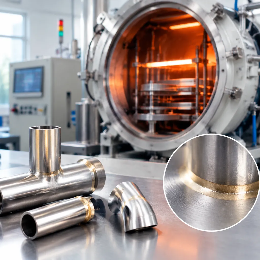
Ideal Joint Clearance for Capillary Action
Capillary flow pulls the molten braze alloy through the joint. To make that happen, you must hit the sweet spot for clearance at actual brazing temperatures, not just at room temperature.
-
- Tight clearances (0.025 mm to 0.05 mm / 0.001" to 0.002"): Best for nickel-based and copper filler metals. This gap size maximizes capillary draw and delivers the highest tensile strength.
- Standard clearances (0.05 mm to 0.10 mm / 0.002" to 0.004"): Common for silver alloys or wider-gap paste applications.
- Excessive clearances (>0.12 mm / 0.005"): Capillary pressure drops drastically. The molten alloy tends to pool, run out of the seam, or form large shrinkage voids as it cools.
Designing Butt, Lap, and Stepped Joints
Different joint configurations carry mechanical loads differently. For industrial vacuum processing, we stick to proven geometry rules:
| Joint Type | Recommended Overlap / Dimension | Best Use Case | Engineering Consideration |
|---|---|---|---|
| Butt Joint | 100% base metal thickness | Low-stress pipe or thin sheet butt-welds | Weak under shear or bending; requires extremely tight alignment. |
| Lap Joint | 3x to 4x the thickness of the thinner member | High-pressure fluid channels, plate assemblies | Delivers joint strength equal to or greater than the parent metal. |
| Stepped Joint | Recessed shoulder matched to wall thickness | Cylindrical parts, tube-to-flange junctions | Self-fixturing; maintains concentricity and controls alloy flow paths. |
Pro Tip: Whenever possible, build self-locating steps or chamfers directly into your CNC parts. Relying on external fixtures inside a vacuum chamber adds thermal mass, slows down cycle times, and drives up overall processing overhead—factors we often evaluate when calculating a vacuum furnace cost and price guide by capacity for production lines.
Accounting for Thermal Expansion in Dissimilar Metals
Joining dissimilar materials—like stainless steel to copper, or tungsten carbide to tool steel—introduces different rates of thermal expansion (CTE).
-
- Male inside Female: Place the material with the higher expansion rate on the outside whenever feasible. As the assembly heats, the outer part expands more, widening the gap so the alloy flows freely. As it cools, the outer part contracts onto the inner part, putting the braze joint into compression rather than tension.
- Reversed Assembly Risks: If the high-expansion metal is on the inside, it expands outward during heating and eliminates the clearance entirely. This starves the joint of braze alloy, leading directly to unbonded sections.
Common Joint Design Mistakes That Cause Dry Joints
-
- Blind Holes Without Venting: Trapped air or outgassing volatiles create backpressure inside a blind cavity. This backpressure literally blows the molten filler metal out of the gap. Always drill a small relief hole or cut a tiny flat on internal pins to let gas escape.
- Excessive Overlap Length: Designing an overlap longer than 4x wall thickness does not add strength. Instead, it increases the risk of trapping gas pockets and fluxless braze voids in the center of the joint.
- Sharp Internal Corners: Sharp transitions cause surface tension breaks. Break edges with a slight radius (0.2 mm to 0.4 mm) to guide the filler metal smoothly across the mating surfaces.
- Ignoring Machining Tolerances: Tolerances stack up quickly. If two mating parts have wide runout limits, one side of the seam might pinch shut while the opposite side opens past 0.15 mm, causing localized joint starvation.
Surface Preparation and Contamination Control
In a vacuum furnace brazing process, cleanliness dictates your success rate. Because we do not use chemical fluxes to dissolve surface films during thermal cycles, the vacuum atmosphere relies entirely on metal-to-metal contact to promote capillary wetting. If your parts enter the chamber dirty, you will face unbonded voids, braze alloy balling, and costly scrap.
Why Oxide Removal Is Critical Before Loading
A high vacuum environment prevents new oxidation from forming during heating, but it cannot dissolve heavy, pre-existing scale or industrial grease.
-
- Wetting Failure: Braze filler metals will not wet or flow over surface oxides. The molten alloy simply beads up, leaving dry joints.
- Outgassing Problems: Oils, coolants, and organic residues vaporize in the hot zone, spiking chamber pressure and contaminating adjacent assemblies.
- Micro-Porosity: Entrapped surface scale creates path channels and pinholes that compromise hermetic sealing.
Understanding these material behaviors is fundamental across diverse vacuum furnace applications, where surface integrity directly controls bonding quality.
Chemical Cleaning, Degreasing, and Acid Pickling
We follow a strict multi-stage chemical cleaning routine to eliminate all shop oils, cutting fluids, and native oxide layers:
-
- Vapor Degreasing / Ultrasonic Bath: Remove machining oils, drawing lubricants, and shop dirt using mild alkaline cleaners or solvent-based degreasers.
- Deoxidizing and Acid Pickling: For stainless steels and nickel alloys, brief chemical pickling strips passive oxide layers. Always neutralize the bath thoroughly.
- High-Purity Deionized (DI) Water Rinse: Wash away all residual cleaning agents. Chemical residues left on the metal will bake into stable films at peak temperatures.
- Hot Air Drying: Dry parts immediately using clean, oil-free compressed air or a heated drying cabinet to prevent flash rust on carbon and alloy steels.
Mechanical Preparation and Surface Roughness Guidelines
Surface profile directly influences capillary pull. If the surface is too smooth, the filler metal lacks micro-grooves to promote wetting. If it is too coarse, capillary action breaks down across wide valleys.
| Surface Condition | Roughness (Ra) Range | Brazing Result |
|---|---|---|
| Mirror Polish | < 0.2 µm (< 8 µin) | Poor wetting; alloy struggles to spread |
| Recommended Finish | 0.4 to 1.6 µm (16 to 63 µin) | Optimal capillary action and uniform flow |
| Coarse Machined | > 3.2 µm (> 125 µin) | Uneven flow, excessive filler pooling, voids |
Shop tip: If you must grit-blast, never use aluminum oxide ($Al_2O_3$). Embedded alumina particles act as stop-offs that completely block braze flow. Use clean stainless steel shot, silicon carbide, or fine glass beads instead, followed by an immediate ultrasonic bath.
Handling, Storage, and Assembly Protocols
Clean parts must stay clean right up to the moment we pump down the chamber:
-
- Wear Clean Nitrile or Lint-Free Gloves: Bare skin leaves body oils and salts. Fingerprints turn into carbonized barriers inside the vacuum hot zone, creating visible bare spots in the braze seam.
- Enforce a Strict Assembly Window: Braze parts within 4 to 8 hours of chemical cleaning. Allowing parts to sit on shop racks for days permits passive oxide films to reform.
- Sealed Storage: If assembly delays happen, seal cleaned components inside clean, dry polyethylene bags with desiccant packs, or hold them in a dry nitrogen purge cabinet.
- Lint-Free Assembly Benches: Assemble your components and apply your brazing filler metal (BFM) on dedicated stainless steel or anti-static surfaces isolated from grinding dust and coolant mist.
Choosing the Right Brazing Filler Metal (BFM)
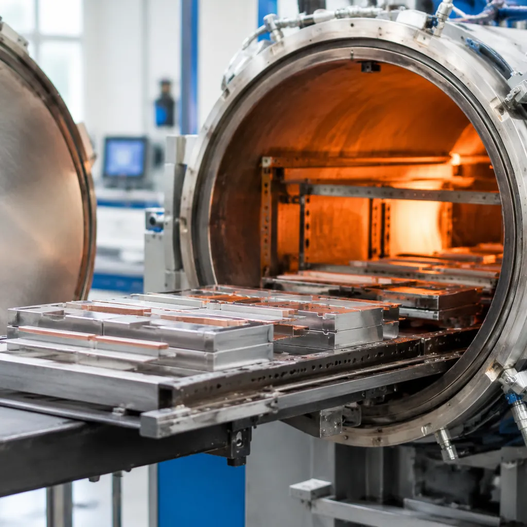
Selecting the right brazing filler metal (BFM) determines whether a joint holds pressure or fails during leak testing. In the vacuum furnace brazing process, base metals do not have chemical fluxes to strip away stubborn oxides. Wetting relies entirely on furnace vacuum integrity and the metallurgical compatibility between your base metal and filler alloy.
Here is how we match the filler metal alloy to the job on our shop floor:
Nickel-Based Filler Metals for High Temperature and Corrosion
When dealing with stainless steel brazing, Inconel, or hot-gas components, nickel braze alloy grades (such as BNi-2, BNi-5, and BNi-7) are the standard choice.
Thermal Performance: Retains high shear strength and oxidation resistance well above 500°C.
Diffusion Behavior: Nickel alloys contain melting point depressants like boron or silicon. Boron diffuses rapidly into the base metal, raising the remelt temperature of the joint, but excessive cycle times can cause base metal erosion.
Copper and Silver Brazing Alloys for General Engineering
For general engineering assemblies, electrical components, and standard carbon-to-stainless joints, copper and silver alloys deliver reliable capillary flow at lower liquidus and solidus temperature profiles.
Pure Copper (BCu-1): Exceptional capillary draw and low cost. Often used on carbon steel and 300-series stainless steel where service temperatures remain moderate.
Silver Alloys (BAg Series): Lower melting ranges reduce thermal distortion on delicate parts. However, volatile elements like zinc or cadmium must never enter a high-vacuum chamber because they vaporize rapidly and foul the hot zone.
Active Braze Alloys (ABA) for Ceramic-to-Metal Bonding
Joining structural ceramics (like alumina, silicon nitride, or zirconia) directly to metals requires an active metal brazing (AMB) approach.
Active braze alloys contain reactive elements—typically titanium—that scavenge oxygen at the interface and form a wet chemical bond directly onto the ceramic face.
Eliminates the costly and labor-intensive molybdenum-manganese (Mo-Mn) metallization step.
Processing specialized or custom braze formulations often requires ultra-clean preparation, identical to melts run in an industrial induction vacuum furnace for high-purity alloys to prevent atmospheric contamination.
BFM Application Methods: Paste, Foil, Wire, and Preforms
How the braze alloy is placed directly affects joint clearance consistency and cycle repeatability:
| Form | Best Used For | Shop-Floor Reality |
|---|---|---|
| Foil & Shims | Flat plate heat exchangers, sandwich assemblies | Provides uniform clearance; ensures exact volume without binder burnout. |
| Pastes | Automated dispensing, complex geometry fillets | Quick to apply, but requires a controlled vacuum preheat soak to outgas organic binders safely. |
| Preformed Wire | Circular joints, tube-to-fitting assemblies | Prevents over-application; seats precisely inside internal grooves. |
Using Stop-Off Paints to Prevent Alloy Migration
Molten filler metal follows heat and capillary pathways, which means it will run directly into screw threads, precision bores, or cooling channels if left unmanaged.
-
- Apply a ceramic-based braze stop-off compound (typically aluminum oxide or yttrium oxide suspensions) along the perimeter of the joint.
- Paint a clean, continuous barrier roughly 1 to 2 mm away from the target fillet.
- Ensure the stop-off vehicle dries completely before pump-down to eliminate braze alloy outgassing and unwanted chamber pressure spikes during heating.
Critical Vacuum Furnace Parameters and Atmosphere Control
Vacuum Level Requirements: Rough vs. High Vacuum
Not every assembly requires an ultra-high vacuum level. Matching the baseline pressure to your base metal and filler chemistry avoids wasted cycle time while protecting joint integrity.
| Vacuum Level | Typical Pressure Range | Common Materials & Processes | Key Pumping Hardware |
|---|---|---|---|
| Rough Vacuum | 10 to 10^-1 Pa | Basic copper brazing, low-alloy steels | Rotary vane or roots mechanical pumps |
| High Vacuum | 10^-3 to 10^-5 Pa | Stainless steels, nickel-based superalloys, titanium | Diffusion or turbomolecular vacuum pumps |
| Partial Pressure | 1 to 200 Pa (with Inert Gas) | Silver/copper-bearing BFMs, zinc prevention | Backfill dosing valve + roughing pump throttling |
Partial Pressure Brazing to Prevent Alloy Vaporization
When brazing with alloys that contain high vapor pressure elements (such as silver, copper, manganese, or zinc), high vacuum can boil these metals right out of the joint before they flow.
To stop this vaporization, we introduce high-purity inert gas—typically grade 5 or 6 Argon, or dry Nitrogen for select stainless runs—to maintain a partial pressure inside the hot zone. If you encounter erratic chamber surges or valve delays during this stage, learning how to fix backfill issues on high vacuum brazing furnace equipment will save your heat exchanger assemblies from immediate oxidation.
Hot Zone Temperature Uniformity and Thermocouple Placement
A pristine vacuum environment means zero heat transfer via convection. Everything depends on radiation, making hot zone temperature uniformity vital:
-
- Multi-Zone PID Tuning: Balance the power inputs across the heating elements so the corners of the furnace do not lag behind the center.
- Workload Thermocouples (TCs): Never rely strictly on control thermocouples mounted near the heating elements. We attach contact TCs directly to the thickest section and the thinnest section of the actual charge.
- The Delta-T Rule: Do not ramp from the preheat soak to the peak brazing temperature until the temperature gap between your thin and thick sections shrinks within ±5°C.
Outgassing Management for Complex Assemblies
Blind tapped holes, braze paste binders, and tightly stacked plates (like microchannel heat exchangers) trap air and solvents. If you blast right past the binder burnout stage, trapped binders crack into carbon deposits that shut down capillary action.
-
- Binder Burnout Holds: Insert a stabilization soak between 350°C and 450°C to allow vacuum pumps to pull away outgassing vapors before heating elements reach peak temperatures.
- Pump Recovery Monitoring: Monitor your vacuum gauge rate of climb. If the chamber pressure spikes during a ramp, pause heating and let the pumps clear the outgassing load before proceeding toward the alloy liquidus point.
Cooling Strategies and Microstructure Control in Vacuum Brazing
Solidification doesn't end the job. In our shop, how we cool a load matters just as much as how we heat it. Managing the cooling curve inside the vacuum furnace brazing process directly dictates joint microstructure, prevents brittle phase precipitation, and keeps assemblies within tight dimensional tolerances.
Radiation Cooling vs. Rapid Gas Quenching
Once the braze alloy drops below its solidus temperature, we choose our cooling method based on part geometry and metallurgical requirements:
-
- In-Furnace Radiation Cooling: We let the load naturally radiate heat toward the water-cooled cold-wall vessel under high vacuum. It offers the lowest thermal distortion for thin foils, delicate honeycomb structures, and complex medical assemblies, though it extends total cycle time.
- Rapid Gas Quenching: To shorten cycle times or lock in specific microstructures, we backfill the chamber with high-purity inert gas and engage high-velocity circulation blowers. Using a single-chamber vacuum furnace with high-pressure gas quenching, we force gas through directional nozzles straight into the hot zone, extracting thermal energy rapidly and evenly.
| Cooling Method | Typical Quench Speed | Distortion Risk | Primary Use Case |
|---|---|---|---|
| Natural Radiation | Slow (hours) | Minimal | Thin gauges, brittle ceramics, complex heat exchangers |
| Forced Convection (1–2 bar) | Moderate | Low | Heavy-section tooling, structural stainless steel |
| High-Pressure Gas Quench (up to 12+ bar) | Extremely fast | Moderate (if uneven) | Simultaneous brazing and hardening of tool steels |
Inert Gas Selection and Quench Pressures
The choice of cooling gas and operating pressure governs heat transfer efficiency:
-
- Argon Gas Quenching: Chemically inert at high temperatures, argon is our default choice for reactive alloys, titanium, and assemblies sensitive to surface nitriding. It provides solid cooling rates at typical working pressures.
- Nitrogen Gas Quenching: Cost-effective and efficient for standard stainless steels, copper joints, and low-alloy steels. We avoid nitrogen on titanium or superalloys due to nitriding risks above 800°C.
- Helium: Offers exceptional thermal transfer rates, but higher operational costs require closed-loop gas recovery systems for volume production.
Preventing Thermal Shock, Warping, and Residual Stress
Thermal gradient mismanagement causes warped assemblies and cracked braze fillets. We eliminate these issues using three practical rules:
-
- Never quench above solidus: Always allow the filler metal alloy to fully freeze into a solid state via vacuum radiation before starting forced gas circulation.
- Program stepped cool-downs: When cooling thick-to-thin joint assemblies, we introduce intermediate stabilization dwells (such as holding at 550°C) to equalize core and surface temperatures.
- Use 360-degree directional gas flow: Multi-directional nozzle rings eliminate localized cold spots, cooling symmetrical and asymmetrical loads evenly without twisting.
Integrating Post-Braze Heat Treatment
We often combine the thermal processing cycle to cut operating costs. Instead of running a separate heating cycle, our vacuum furnaces allow us to complete the braze dwell, cool down to austenitizing or solution-annealing temperatures, and execute a controlled gas quench. When cycle speed is critical for hardening tool steels directly after joint consolidation, running a dedicated quick-quench vacuum furnace saves hours of production time while keeping the brazed joints bright and oxide-free.
Troubleshooting Common Vacuum Brazing Defects
Running a vacuum furnace brazing process demands tight process discipline. When assemblies exit the chamber with visible flaws, leak-test failures, or weak bonds, isolating the root cause quickly keeps scrap rates down and production moving.
| Defect Observed | Primary Root Cause | Practical Shop-Floor Fix |
|---|---|---|
| Voids & Incomplete Fill | Dirty joint surfaces or excessive gap clearance | Degrease parts thoroughly; adjust joint gap to capillary tolerances ($0.025$ to $0.05$ mm). |
| Base Metal Erosion | Brazing temperature too high or dwell too long | Lower peak temperature closer to alloy liquidus; reduce soak time at peak. |
| Surface Discoloration | Air ingress or contaminated cooling gas | Helium leak-check the chamber; upgrade purge gas purity. |
| Part Distortion | Uneven heating rates or aggressive quench pressure | Slow the ramp rates; optimize multi-zone PID control; reduce gas backfill pressure. |
Fixing Voids, Porosity, and Incomplete Joint Fill
Gaps and voids inside the seam usually point back to two main culprits: poor capillary draw or surface contaminants.
-
- Clearance issues: If your joint clearance is wider than the alloy can bridge via capillary action, the molten filler metal pools instead of drawing through. Tighten dimensional tolerances before loading.
- Surface contamination: Residual drawing oils, finger oils, or stubborn surface oxides stop the brazing filler metal (BFM) from wetting the base metal. Improve upstream solvent degreasing and ultrasonic cleaning steps.
- Insufficient filler volume: If you see gaps alongside smooth fillets, verify your preform, paste, or foil volume calculations.
Diagnosing Base Metal Erosion and Excessive Alloy Diffusion
Base metal erosion happens when the molten filler dissolves into the thin walls of your assembly, weakening the core structure.
-
- Overheating: Running the furnace even 15°C to 20°C above the recommended brazing liquidus drastically accelerates base-metal scavenging, especially with nickel-based alloys on thin stainless steel.
- Excessive dwell time: Holding the parts at peak brazing temperature too long allows unnecessary diffusion into the grain boundaries. Shorten the dwell time once the braze reaches liquidus.
- Alloy over-application: Applying too much filler metal creates a larger chemical reservoir to aggressively attack base metals. Use precisely measured preforms rather than arbitrary paste beads.
Causes of Joint Discoloration and Oxidation Leaks
A properly executed vacuum run should deliver bright, clean parts right out of the hot zone. If parts come out discolored or dull:
-
- Vacuum chamber leaks: Micro-leaks in door seals, feedthroughs, or valve gaskets allow oxygen and moisture into the hot zone during the cycle. Check your leak-up rates before every critical run.
- Backfill gas contamination: If parts oxidize during the cooling phase, review why copper parts discolor during vacuum furnace backfill to understand how moisture or low-purity backfill gas ruins surface finish. Ensure your nitrogen or argon supplies maintain high purity levels.
- Premature unloading: Opening the furnace door before parts drop below 150°C to 200°C exposes hot metal surfaces to ambient air, causing instant oxidation tinting.
Preventing Assembly Distortion and Joint Misalignment
High thermal cycles naturally relax stresses, which can throw tight assembly tolerances out of spec if not handled correctly.
-
- Uneven ramp rates: Heating too quickly causes thin structural sections to expand long before heavy sections catch up. Introduce thermal stabilization soaks to allow the entire load to equalize.
- Inadequate fixturing: Use low-mass fixtures made from materials with compatible thermal expansion rates (such as molybdenum, stainless steel, or graphite) to support components without over-constraining thermal movement.
- Violent gas quenching: Blasting high-pressure inert gas directly at delicate assemblies induces thermal shock and warps thin sheets. Balance the cooling cycle by directing fan nozzles evenly or lowering quench pressures.
Vacuum Furnace Brazing FAQs
When managing a production run or dialing in new part designs, questions always pop up on the shop floor. Here are the practical, direct answers to the most common questions we get about the vacuum furnace brazing process.
Do You Need Flux for Vacuum Furnace Brazing?
No. The entire point of running a fluxless brazing technique in a vacuum furnace is eliminating chemical fluxes completely.
-
- Why it works: High vacuum levels strip existing surface oxides at elevated temperatures and stop new oxides from forming.
- The payoff: You avoid corrosive residues, skip costly chemical wash cycles, and eliminate internal joint porosity caused by trapped flux gas.
What Vacuum Level Is Required for Stainless Steel Brazing?
For clean stainless steel brazing without surface discoloration, we maintain an operating vacuum of 10⁻³ Pa to 10⁻⁵ Pa (high vacuum range).
Chromium-rich alloys oxidize instantly if oxygen or moisture lingers in the chamber. If you braze with nickel or copper filler metals, a solid diffusion pump system pulling down into the 10⁻⁴ Pa zone before reaching braze temperature prevents chromium oxide from forming, ensuring full capillary wetting across the joint.
Can You Braze Titanium in a Standard Vacuum Furnace?
You can, but only if the furnace meets strict atmosphere purity standards. Titanium acts like an active sponge for oxygen, nitrogen, and hydrogen above 400°C.
-
- Hot zone requirements: An all-metal hot zone (molybdenum or tungsten elements with metallic shielding) is strongly preferred over graphite to prevent carbon pickup.
- Leak rate: The furnace chamber must demonstrate exceptionally low leak-back rates. We typically demand high vacuum levels of at least 10⁻⁴ Pa to 10⁻⁵ Pa along with ultra-high-purity inert gas for cooling.
How Long Does a Typical Vacuum Brazing Cycle Take?
A standard thermal processing cycle generally spans 4 to 10 hours from door closure to unload, depending on three primary variables:
| Cycle Factor | Impact on Run Time | Typical Target |
|---|---|---|
| Workload Mass | Heavy fixtures and dense loads require longer thermal stabilization soaks | 30 to 90 min per soak stage |
| Braze Dwell Time | Holding above alloy liquidus to allow complete capillary flow | 5 to 20 minutes |
| Cooling Method | Natural furnace cooling vs. high-pressure argon gas quenching | Quench reduces cooling by hours |
When cycle speed and high throughput are critical, deploying a specialized unit like a double-chamber vacuum furnace for precision heat treatment separates the heating and cooling zones to cut overall cycle times significantly.
How Do You Inspect the Quality of a Vacuum-Brazed Joint?
Evaluating braze integrity requires a combination of visual, non-destructive, and destructive methods:
-
- Visual Inspection: We look for a continuous, smooth braze fillet along the entire joint seam with zero discoloration, spatter, or un-melted filler metal.
- Helium Mass Spectrometry: The industry standard for vacuum-tight assemblies, plate heat exchangers, and fluid lines to detect micro-leaks.
- Ultrasonic or X-Ray Testing (NDT): Identifies internal voids, gas pockets, and incomplete capillary penetration inside closed joints.
- Metallographic Sectioning: Periodic destructive sampling where we cut, polish, and etch sample joints under a microscope to evaluate alloy diffusion, fillet geometry, and base metal erosion.