
Diagnosing Discolored Copper Parts from Vacuum Brazing Furnaces
Pulling a load of discolored copper parts from a vacuum brazing furnace is an immediate red flag for process contamination. When copper assemblies exit the hot zone with pink, purple, dark brown, or cloudy finishes instead of a bright, clean, metallic luster, surface chemistry has failed.
Identifying the exact color and texture of the surface layer allows us to pinpoint the precise thermal and atmospheric failure points in the brazing cycle.
Visual Appearance Breakdown:
├── Salmon Pink / Ruby / Purple ──> Cuprous Oxide (Cu2O) ──> Low partial pressure O2 / Mid-temp cooling
├── Dark Brown / Matte Black ──> Cupric Oxide (CuO) ──> High O2 concentration / Gross vacuum leak
└── Milky / Cloudy White Haze ──> Surface Films ──> Volatilization / Residual carbon & organics
Deciphering Copper Discoloration: Visual Appearance vs. Oxide Formation
Copper reacts rapidly with trace oxygen, moisture, and hydrocarbons at elevated temperatures. The resulting hue indicates the oxidation state and the specific environment inside the vacuum chamber during heating, soak, or cooling.
| Visual Appearance | Primary Compound | Typical Root Cause | Process Stage |
|---|---|---|---|
| Salmon Pink / Light Red | Cuprous Oxide (Cu2O) | Trace oxygen exposure ($< 10$ ppm $O_2$) | High-temp soak or early cooling |
| Iridescent Purple / Blue | Thin-film Cuprous Oxide | Low partial pressure moisture/oxygen | Intermediate cooling (300 °C - 500 °C) |
| Matte Brown to Jet Black | Cupric Oxide (CuO) | High oxygen concentration ($> 100$ ppm $O_2$) | Atmospheric breach or gross leak |
| Milky White / Gray Haze | Carbon / Volatilized Flux | Solvent residue or alloy binder breakdown | Outgassing during initial ramp-up |
Cuprous Oxide (Cu2O): Reddish, Salmon Pink, and Purple Tones
When copper encounters minimal levels of oxygen under reduced pressure, it forms cuprous oxide (Cu2O).
-
- Formation Conditions: Occurs under low partial pressure of oxygen or when discolored copper parts from vacuum brazing furnace systems cool through the 300 °C to 550 °C (572 °F - 1022 °F) range.
- Mechanism: In a tight vacuum, even tiny trace leaks or marginal gas purity levels provide enough oxygen molecules to convert the outer monolayer into Cu2O without generating thick scale.
- Diagnostic Clue: If the parts emerge uniform salmon-pink or iridescent purple, the furnace maintained basic vacuum integrity, but suffered minor oxygen exposure or elevated moisture during the cycle.
Cupric Oxide (CuO): Brown and Black Scale
The formation of cupric oxide (CuO) represents a severe process failure where copper oxidizes fully due to substantial oxygen saturation.
-
- Formation Conditions: Heavy air ingress, gross vacuum chamber leaks, water jacket breaches, or premature door openings above 150 °C (300 °F).
- Mechanism: Excess oxygen reacts with existing cuprous oxide to form a thick, non-adherent black or dark-brown CuO scale.
- Diagnostic Clue: Flaking black scale points to mechanical seal failures, power loss during high-temperature cycles, or massive air ingress into the chamber.
Hazy or Milky Staining: Volatilization and Carbon Residues
Non-oxide surface defects manifest as cloudy, gray, or white films that do not match traditional copper oxide colors.
-
- Residual Carbon Films: Hydrocarbons from cutting fluids, forming lubricants, or improper degreasing solvents crack at elevated temperatures, leaving a diffuse carbon film on the copper.
- Surface Volatilization: High-vapor-pressure elements (such as zinc or phosphorus from specific braze alloys) volatilize in high vacuum and redeposit across the copper surfaces as a dull, milky film.
- Diagnostic Clue: If the discoloration wipes off with an alcohol wipe or does not respond to standard acid pickling, pre-wash cleanliness or alloy vapor pressure control is the primary issue.
Root Causes of Discolored Copper Parts from Vacuum Brazing Furnace During Heating and Soaking
Inadequate Ultimate Vacuum Level and Chamber Rate-of-Rise
A weak vacuum level is the most common reason copper loses its bright finish during thermal processing. Copper requires a clean, high-vacuum environment to prevent the formation of cuprous and cupric oxides during temperature ramp-up.
-
- High Leak-Up Rate: Even if your roughing and high-vacuum diffusion or turbomolecular pumps pull the chamber down, a high rate-of-rise (leak-up rate) allows atmospheric oxygen to continuously enter the chamber.
- Insufficient Base Pressure: Starting your heating cycle before reaching the target vacuum level triggers rapid surface tarnishing. Following a proven vacuum furnace brazing cycle guide and process parameters ensures the chamber reaches acceptable base vacuum levels before the heating elements energize.
- Dynamic Micro-Leaks: Thermal expansion during the heating cycle can cause seal degradation at feedthroughs, sight glasses, or door O-rings that do not show up during cold static checks.
Hot Zone Outgassing at Elevated Temperatures
Furnace insulation, heating elements, and fixturing absorb atmospheric moisture every time the furnace door opens to the shop floor.
-
- Moisture Desorption: As the hot zone heats up between 200°C and 600°C, porous insulation materials desorb trapped water vapor directly into the processing atmosphere.
- Localized Oxygen Contamination: This released moisture breaks down at brazing temperatures, generating free oxygen that immediately attacks copper surfaces, resulting in dull red, purple, or cloudy discoloration.
- Contaminated Fixtures: Graphite or ceramic fixtures holding the copper assemblies can release binder residues and absorbed moisture if they are not routinely pre-baked under vacuum.
Pre-Brazing Surface Contamination and Residues
Chemical residues left on copper components crack and oxidize at elevated temperatures, leaving distinct stains that look like furnace atmospheric oxidation.
| Contaminant Type | Thermal Reaction | Visual Defect on Copper |
|---|---|---|
| Machining Oils / Lubricants | Hydrocarbon cracking at high heat | Dark brown or black carbonized staining |
| Fingerprints / Handling Oils | Salt and localized surface oxidation | Distinct localized patterns and etching |
| Solvent Residues | Incomplete drying before pump-down | Milky white or hazy surface film |
| Pre-existing Oxides | Uneven reduction under vacuum | Blotchy, non-uniform copper coloration |
To eliminate heating-stage discoloration, thoroughly degrease all assemblies, monitor the chamber rate-of-rise before every cycle, and ensure the hot zone is fully decontaminated.
Why Copper Discolors During Backfill and Cooling
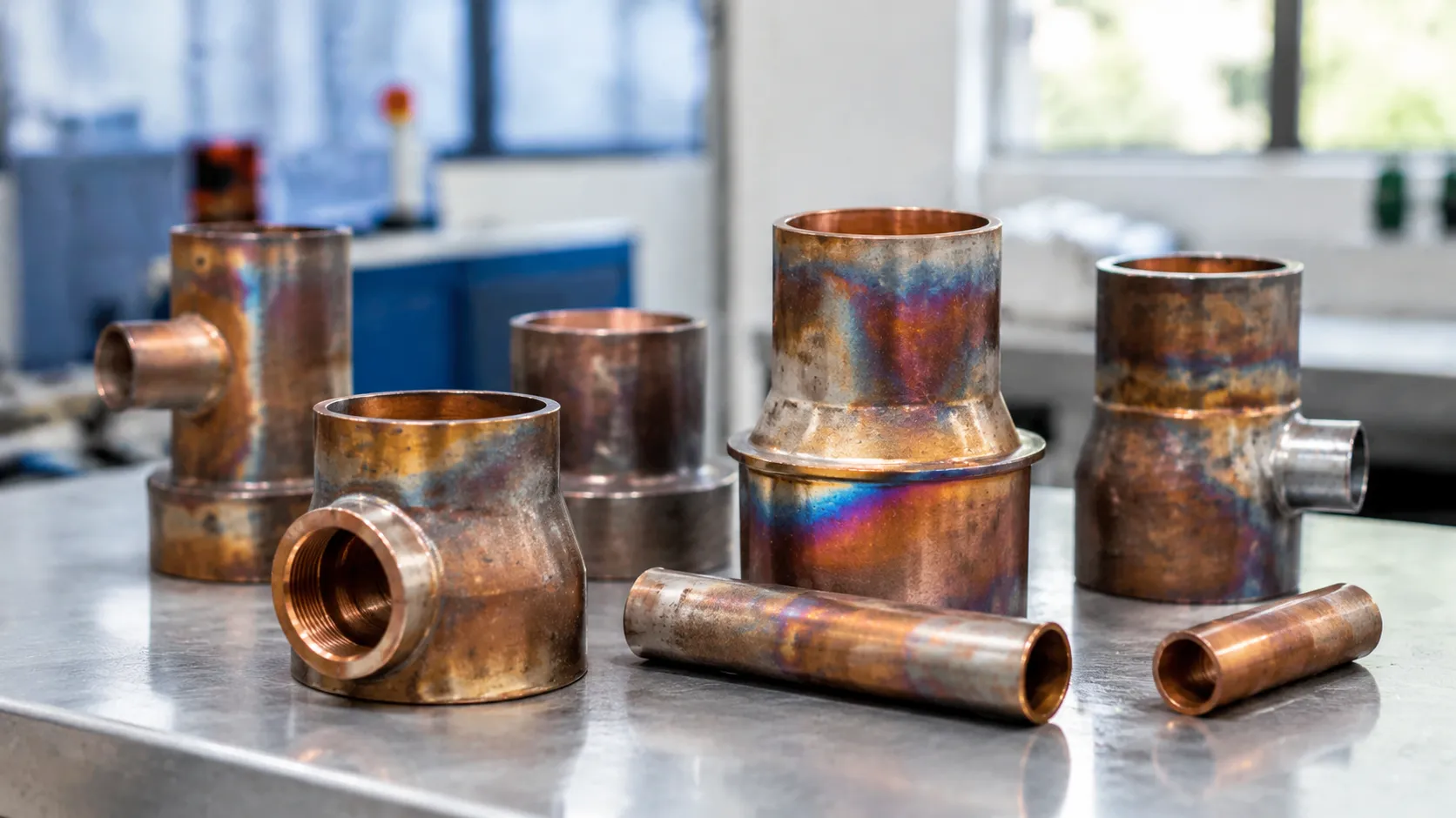
Pulling discolored copper parts from vacuum brazing furnace during backfill is one of the most frustrating issues on the shop floor. When assemblies look pristine under vacuum but exit the cooling cycle with pink, purple, or black surface films, the contamination is entering directly through the gas quenching sequence.
Understanding the atmosphere dynamics across standard vacuum furnace applications helps isolate why inert gas cooling cycles trigger rapid oxidation on hot copper surfaces:
-
- Gas Purity and Trace Contaminants: Standard industrial-grade argon or nitrogen contains sufficient oxygen (typically >10 to 50 ppm) to ruin bright copper finishes. We always mandate Ultra-High Purity (UHP) gases (99.999% purity, with $O_2$ levels under 1 to 2 ppm). Even minute levels of oxygen will instantly react with hot copper during forced convection cooling.
- Dew Point Deficiencies in Supply Lines: Moisture ($H_2O$) is a aggressive oxidizer of hot copper. Bulk gas tanks, vaporizers, and distribution lines must maintain a dew point of -60°C (-76°F) or drier at the point of injection. Saturated supply filters, unbaked flex hoses, or condensation in cold manifolds will spike the dew point and discolor parts immediately.
- Premature Backfill Initiation Temperature: Copper begins oxidizing readily in trace-moisture environments at temperatures as low as 150°C to 200°C (300°F to 392°F). Initiating high-pressure backfill while the core load remains above these threshold temperatures guarantees surface oxidation if the gas has even slight impurity levels.
- Venturi-Effect Air Ingress and Piping Dead Legs: High-velocity gas flow through backfill valves creates a localized low-pressure zone. If solenoid valves, O-rings, or pipe fittings have micro-leaks, atmospheric air is drawn directly into the gas stream via the Venturi effect. Furthermore, unpurged "dead legs" in the supply manifold harbor trapped air and moisture that gets swept directly into the hot zone during initial injection.
Step-by-Step Troubleshooting Protocol for Furnace Operators
When you pull a load of discolored copper parts from vacuum brazing furnace runs, running random trial batches wastes time and scrap allowance. We recommend following a structured diagnostic sequence to isolate whether the root cause stems from base vacuum leakage, gas contamination, or thermal timing errors.
Phase 1: Vacuum System Integrity Verification
Before blaming the process gas, confirm that the hot zone and vessel seals are tight.
-
- Perform a Standard Rate-of-Rise (RoR) Test: Pump the empty chamber down to ultimate vacuum, isolate the pumping stack, and log the pressure increase over 30 to 60 minutes. An acceptable baseline for clean copper brazing is typically below 5 to 10 microns (0.005 to 0.010 mbar) per hour.
- Pinpoint Micro-Leaks with Helium Mass Spectrometry: If the leak-up rate fails specifications, use a helium mass spectrometer leak detector to probe all feedthroughs, door O-rings, pneumatic valve stems, and sight glasses.
- Inspect Hot Zone Loading Configurations: When running a high-temperature cycle in a top-loading vacuum furnace or front-loading chamber, verify that power feedthrough O-rings have not degraded from heat radiation.
Phase 2: Backfill Gas and Delivery Piping Diagnostics
If vacuum levels are solid but you still see discolored copper parts from vacuum brazing furnace during backfill, trace the entire gas injection train.
-
- Measure Point-of-Use Gas Purity: Never rely solely on bulk tank certifications. Place an in-line oxygen analyzer directly at the furnace gas inlet manifold to verify levels remain under 1 ppm.
- Monitor In-Line Dew Point: Install a calibrated ceramic or chilled-mirror hygrometer on the backfill line. The dew point must read -60°C (-76°F) or lower during active gas flow.
- Check for Venturi Air Ingress: Inspect all fast-cooling relief valves, bypass lines, and regulator fittings. High-velocity gas flow through loose pipe joints can pull ambient air into the delivery stream, introducing moisture directly during backfill pressurization.
Phase 3: Thermal Profiling and Load Thermocouple Audits
Surface discoloration frequently happens when the cooling cycle initiates before the core and dense sections of the load have safely cooled.
-
- Audit Core vs. Surface Temperatures: Do not rely exclusively on furnace control thermocouples. Attach trailing load thermocouples directly to the thickest copper sections and the center of the fixture.
- Establish Safe Backfill Thresholds: Keep the load under high vacuum until all parts drop below 150°C to 200°C (300°F to 392°F) before opening cooling valves.
- Map Hot Zone Uniformity: Run a multi-point temperature uniformity survey (TUS) to identify stagnant radiation zones where heavy copper components retain heat longer than the control panel indicates.
Engineered Corrective Actions and Process Optimization
Atmosphere Conditioning with In-Line Gas Purifiers and Moisture Traps
Bulk gas delivery systems often pick up micro-contaminants along distribution manifolds. To safeguard your cycle:
Install Point-of-Use Gas Purifiers: Position heated catalytic purifiers directly at the furnace gas inlet to strip oxygen down below 1 ppm.
Integrate Desiccant & Cryogenic Moisture Traps: Strip residual moisture to consistently maintain a backfill dew point below -60°C (-76°F).
Upgrade Gas Lines to Stainless Steel: Replace all copper or elastomer flex hoses with electropolished 316L stainless steel tubing with metal gasket face seal fittings to stop atmospheric diffusion.
Automated Temperature Interlock Controls to Prevent Premature Backfill
Introducing cooling gas too early is the leading trigger for discolored copper parts from vacuum brazing furnace during backfill.
Hard Interlock Programming: Program the furnace PLC to mechanically lock out the backfill valve until the load thermocouples indicate the core temperature has dropped below 200°C (392°F).
Load-Triggered (Not Retort-Triggered) Logic: Base your cooling recipes strictly on interior work thermocouples, not exterior zone sensors, avoiding premature gas injection while the dense copper core is still hot.
For rapid production without oxidation risks, modern equipment like our single-chamber vacuum furnace with high-pressure gas quenching integrates automated backfill interlocks and precise pressure regulation to guarantee clean, bright metallurgical results.
Rigorous Pre-Cleaning Protocols: Ultrasonic Degreasing and Pickling
Pre-existing surface films carbonize or react under vacuum:
Multi-Stage Ultrasonic Solvent Degreasing: Remove all machining oils, drawing lubricants, and shop grease before assembly.
Mild Acid Pickling & Passivation: Strip native cuprous oxide films using a dilute citric or sulfuric acid bath, followed by a deionized water rinse and rapid warm-air drying.
Strict Handling Controls: Mandate clean lint-free gloves during assembly. Skin oils leave distinct fingerprint stains that bake directly into the copper surface.
Routine High-Temperature Vacuum Bake-Out Cycles
Furnace insulation and heating elements absorb moisture and volatile binder residue every time the chamber opens to ambient air.
Run an empty-chamber bake-out cycle weekly or after every major maintenance shutdown.
Ramp the furnace to at least 50°C to 100°C above your normal brazing temperature under deep vacuum.
Hold at peak temperature until the chamber outgassing drops and the ultimate vacuum level stabilizes, stripping moisture and volatile species from graphite or metallic heat shields before running production copper loads.
Advanced Vacuum Furnace Features for Bright Brazing
Preventing discolored copper parts from vacuum brazing furnace runs requires equipment designed to eliminate air ingress and thermal stagnation. We build our vacuum systems with hardware safeguards that keep copper assemblies bright, clean, and free of oxide layers.
| Engineering Feature | Technical Mechanism | Defect Prevention |
|---|---|---|
| Ultra-Low Leak Chamber & High-Vacuum Pumping | Multi-stage diffusion and turbomolecular pumps with double-sealed viton O-rings | Eliminates micro-leaks and maintains low rate-of-rise to stop high-temperature oxidation |
| Automated Backfill Management | In-line dew point sensors, purge cycles, and automated gas valves | Prevents discolored copper parts from vacuum brazing furnace during backfill by blocking wet gas |
| Uniform Quenching Gas Manifolds | 360-degree radial nozzle arrays and balanced plenum injection | Avoids thermal gradients and localized hot spots during inert gas cooling |
Ultra-Low Leak Rate Chamber Designs and High-Vacuum Pumping
A stable base vacuum prevents oxidation during the heat cycle. We use stainless steel water-cooled vessels with minimal weld joints, automated isolation valves, and multi-stage vacuum pumping packages. This setup achieves rapid pump-down times and maintains an ultra-low rate-of-rise throughout high-temperature brazing plateaus.
Automated Gas Backfill Management
Moisture and oxygen spikes during cooling remain the main reasons for surface staining. Our furnace controls integrate real-time dew point monitoring, automated line pre-purging, and closed-loop pressure regulators. Understanding how to fix backfill issues on high vacuum brazing furnace systems starts with setting automated interlocks that prevent gas introduction until the load drops below critical oxidation thresholds.
Uniform Gas Quenching Distribution Manifolds
Uneven gas injection creates cold spots and leaves trailing hot zones exposed to trace impurities. We incorporate 360-degree gas distribution nozzles linked to high-flow heat exchangers and high-performance blowers. For operations requiring rapid, balanced cooling across heavy charges, advanced vacuum gas quenching pressure systems ensure rapid, symmetrical heat removal, keeping copper surfaces completely bright from center to edge.
Frequently Asked Questions About Vacuum Brazing Copper Discoloration
What is the maximum acceptable dew point for backfill gas when brazing copper?
We recommend maintaining an inert gas dew point of -60°C (-76°F) or lower at the furnace inlet. To completely eliminate discolored copper parts from vacuum brazing furnace operations, high-reliability processes should target a dew point between -65°C and -70°C. A dew point higher than -40°C introduces sufficient moisture ($H_2O$) to trigger rapid surface oxidation across copper assemblies during cooling.
At what temperature is it safe to backfill nitrogen or argon over copper components?
Never initiate gas quenching while the workload is at brazing heat. The safe threshold for backfilling inert gas is when the copper core temperature drops below 200°C (392°F). For mirror-bright or OFHC copper parts sensitive to trace ppm oxygen, we hold the vacuum cooling cycle until the load falls below 150°C (302°F) before introducing backfill pressure. Introducing cooling gas above these thresholds is the primary reason operators see discolored copper parts from vacuum brazing furnace during backfill cycles.
Can discolored copper parts be reclaimed without compromising brazed joint integrity?
Yes, depending on the severity of the oxidation layer:
Light cuprous oxide (salmon, pink, or light purple): Reclaim through mild acid pickling using a 5% to 10% sulfamic or citric acid solution, followed by immediate deionized water rinsing and forced hot-air drying.
Heavy cupric oxide (brown or black scaling): Requires mechanical glass-bead blasting or chemical etching, though care must be taken not to erode thin-walled parent materials or brazed fillet geometries.
Thermal reduction: Running a vacuum cycle with a partial pressure of dry hydrogen or cracked ammonia can reduce light surface oxides without mechanical handling.
Why are only the parts near the gas injection nozzles discolored?
When discoloration concentrates strictly near the gas injection ports or plenum nozzles, the root cause is almost always localized gas contamination. This happens due to:
Gas line dead legs: Moisture and air trapped in delivery manifolds get blasted onto the hottest parts during the initial gas surge.
Venturi-effect air ingress: A micro-leak in the backfill valve or piping pulls room air into the high-velocity inert gas stream.
Direct gas impingement: Cold, unpurified gas striking parts that are still above safe oxidation temperatures.
Ensuring proper manifold purging and utilizing a dedicated diamond milling cutter vacuum brazing furnace with engineered gas distribution helps maintain uniform atmosphere purity and surface brightness across the entire load.