Metallurgical Fundamentals Governing Quench Pressure Selection
Choosing the right vacuum gas quenching pressure—whether 6, 10, 12, 20, or 25 bar—is an engineering decision dictated by alloy chemistry, part geometry, and microstructure requirements. In high-pressure gas quenching (HPGQ), our primary objective is to extract heat rapidly and uniformly to achieve optimal metallurgical transformation without triggering destructive thermal stress.
Cooling Rate vs. Microstructural Transformation
Temperature (°C)
1000 |--------------------\ [Austenitizing Zone]
800 |-------\ \
| \ Pearlite \
600 | ( Nose ) \ <-- Critical 800°C to 500°C Zone
400 |----------\ \ (Fast quench bypasses nose)
200 | \ \---> Martensite Start (Ms)
0 |__________________________\___ [100% Martensitic Matrix]
0.1 1.0 10 100 1000 Time (Seconds)
Critical Cooling Rates on CCT Diagrams
Every steel grade exhibits a unique Continuous Cooling Transformation (CCT) diagram that defines its transformation behavior:
-
- Bypassing the Nose: To achieve full martensitic transformation and reach peak hardness, the cooling rate must bypass the ferrite, pearlite, and upper bainite "noses" on the CCT curve.
- The 800°C to 500°C Window: This represents the most critical thermal zone. Any delay in heat extraction across this range allows non-martensitic phases to precipitate, degrading core strength, wear resistance, and toughness.
- Convective Heat Transfer: Increasing quenching pressure from 6 bar to 25 bar directly raises process gas density ($N_2$ or $Ar$) and the convective heat transfer coefficient, accelerating thermal extraction through this phase-transition window.
Cross-Sectional Mass Effect and Ruling Section Limits
Workpiece geometry and thickness fundamentally dictate heat dissipation rates:
-
- Thermal Conductivity Limits: The interior core of a component can only transfer heat outward as fast as the material's internal thermal conductivity allows.
- Core vs. Surface Hardness: As section thickness increases, the cooling velocity at the center drops. If the cooling rate falls below the alloy's critical threshold, core hardness drops significantly.
- Pressure Sizing for Ruling Sections: Lean-alloy steels and heavy solid sections demand significantly higher gas pressures (16 to 25 bar) to generate the surface-to-core thermal gradient necessary to maintain core hardenability across thick sections.
Balancing Quench Severity to Control Distortion and Cracking
Achieving metallurgical hardness must not come at the expense of geometric stability:
-
- Thermal Gradient Management: Quenching too aggressively creates wide temperature differentials ($\Delta T$) between outer surfaces and the center mass, generating high residual stresses that lead to warping or cracking.
- Controlled Quench Intensity: We optimize pressure levels alongside high-velocity, multi-directional gas recirculation (such as 360 ° annular nozzle arrays) to produce uniform cooling vectors across complex geometries.
- Distortion Reduction: Matching the minimum necessary gas pressure to the alloy's hardenability curve prevents over-quenching, delivering fully transformed martensitic parts while eliminating post-quench straightening operations.
6 to 10 Bar Quenching for Medium-High Pressure Applications
For standard tool and die shops, setting your vacuum gas quenching pressure between 6 and 10 bar delivers reliable hardness without overworking your gas supply or inducing unnecessary part movement. This pressure band fits alloys with high hardenability, allowing nitrogen gas cooling to bypass the pearlite nose on the CCT diagram efficiently across moderate cross-sections.
| Steel Grade | Typical Components | Max Ruling Section | Target Hardness |
|---|---|---|---|
| AISI D2 / 1.2379 | Forming dies, shear blades | Up to 100 mm (4 in) | 58–62 HRC |
| AISI H13 / 1.2344 | Extrusion dies, molds | Up to 90 mm (3.5 in) | 46–52 HRC |
| AISI A2 / 1.2363 | Punches, stamping dies | Up to 100 mm (4 in) | 57–62 HRC |
| AISI 420 / 1.4021 | Cutlery, valve components | Up to 75 mm (3 in) | 50–54 HRC |
Ideal Workpiece Profiles and Ruling Sections Under 100 mm
We regularly configure our single-chamber vacuum furnace with high-pressure gas quenching within the 6 to 10 bar window for workloads dominated by air-hardening steels.
-
- Section Thickness Limits: Solid blocks and round tooling with effective ruling sections under 100 mm achieve uniform martensitic transformation through the core.
- Complex Geometry Support: Slender punches, progressive stamping tools, and plates with asymmetric cooling channels benefit from the moderate convective heat transfer coefficient at 8–10 bar, preventing quench cracks.
- Surface Integrity: High-purity nitrogen gas quenching keeps surfaces clean and bright, eliminating post-quench acid pickling or heavy grit blasting.
Operational Benefits: Distortion Control and Lower Gas Consumption
Running at 6 to 10 bar instead of ultra-high pressures provides immediate economic and metallurgical advantages:
-
- Minimal Part Distortion: Moderate gas velocity reduces aerodynamic drag across delicate profiles, cutting down on post-heat-treatment grinding allowances.
- Lower Operating Costs: Gas fill volume per quench cycle drops by more than 50% compared to a 20-bar cycle, lowering liquid nitrogen vaporization costs and reducing blower motor peak amperage.
- Reduced Blower Wear: Centrifugal cooling fans operate under lower back-pressure, extending motor, bearing, and dynamic seal life.
Performance Limits on High-Speed and Low-Alloy Steels
While 6 to 10 bar handles standard tool steels with ease, it hits clear metallurgical boundaries when processing more demanding alloys:
-
- High-Speed Steels (HSS): Grades like AISI M2, M35, or M42 demand faster cooling across the 800°C to 500°C range to avoid grain boundary carbide precipitation. At 10 bar, sections above 40 mm often suffer reduced secondary hardness after tempering.
- Low-Alloy Structural Steels: Steels such as 4140, 4340, or 8620 possess shallow hardenability curves. In sections over 30 mm, a 6 to 10 bar quench cannot extract heat fast enough, yielding unwanted bainite or ferrite in the core rather than full martensite.
12 to 16 Bar Quenching for Heavy Tooling and High-Speed Steels
When component cross-sections expand or steel alloys require steeper cooling gradients, stepping up to 12 to 16 bar vacuum gas quenching pressure bridges the gap between standard gas cooling and liquid quenching. At our facility, we configure these intermediate high-pressure parameters specifically for heavy tooling packages that require deep hardenability without risking quench cracking.
Target Alloys and Cross-Sections up to 150 mm
Operating within the 12 to 16 bar window provides the necessary convective heat transfer rates for:
Hot-Work Tool Steels: Large AISI H13, H11, and 1.2344 die-casting blocks exceeding 100 mm to 150 mm in solid thickness.
High-Speed Steels (HSS): AISI M2, M7, and matrix tooling steels where carbide precipitation along grain boundaries must be strictly avoided.
Heavy Shafts and Chunky Dies: Heavy-mass tooling where core hardness must match surface hardness within tight tolerances.
Clearing the Critical 800°C to 500°C Danger Zone
The primary metallurgical goal at 12 to 16 bar is beating the "nose" of the Continuous Cooling Transformation (CCT) diagram. Between 800°C and 500°C, cooling delay can cause unwanted bainitic or pearlitic phase transformations, ruining impact toughness.
By utilizing 12 to 16 bar pressurized nitrogen, we dramatically increase the gas density and velocity, ensuring the core of a 150 mm steel block bypasses this critical zone fast enough to achieve a 100% martensitic transformation upon final cooling.
Demands on Furnace Hardware and Engineering
Quenching at 12 to 16 bar places extreme mechanical and thermal demands on the furnace architecture. Our high-performance vacuum heat treating systems manage this through heavy-duty engineering:
High-Power Centrifugal Blowers: Driven by high-output motors to propel dense gas charges at high velocity through tight workpiece loads.
High-Efficiency Copper Heat Exchangers: Sized to rapidly strip heat from the recirculating gas stream before it re-enters the hot zone.
360-Degree Directional Nozzles: Encircling the charge to ensure symmetrical cooling fronts, preventing uneven thermal stress and dimensional distortion across asymmetrical tooling profiles.
20 to 25 Bar Ultra-High Pressure Gas Quenching
When treating low-hardenability steels or massive tooling cross-sections, a standard 6 to 12 bar quench cycle is not aggressive enough to beat the nose of the continuous cooling transformation (CCT) curve. Operating at a vacuum gas quenching pressure of 20 to 25 bar bridges the gap between conventional gas quenching and liquid oil quenching, delivering the heat transfer rates needed for the most demanding alloys.
Target Alloys and Applications
At 20 to 25 bar, the high-density gas flow extracts heat fast enough to process materials that historically required salt or oil quenching:
Powder Metallurgy (PM) Tool Steels: Alloys such as CPM 10V, Vanadis 4 Extra, and S390 requiring rapid cooling rates to prevent carbide precipitation at grain boundaries.
High-Alloy High-Speed Steels (HSS): Heavy-section cutting tools made from M35, M42, and T15 where peak red-hardness and core toughness are non-negotiable.
Low-Alloy Carburizing Steels: Transmission gears, shafts, and automotive pinions processed via low-pressure carburizing (LPC) using alloys like 20MnCr5, 8620, or 5120.
Replacing Oil Quenching for Clean, Bright Workpieces
Running a 25 bar vacuum furnace eliminates the traditional drawbacks of liquid quench lines:
Zero Post-Quench Cleaning: Parts emerge bright, clean, and dry, completely bypassing wash tanks, degreasers, and environmental disposal costs for quench oil.
Elimination of Vapor Blanketing: Gas quenching maintains uniform contact across complex geometries, avoiding the soft spots and asymmetric distortion caused by boiling oil vapor pockets.
Full Core Hardness in Heavy Sections: Provides critical convective heat transfer capable of fully through-hardening solid blocks and tool shafts exceeding 200 mm in ruling section.
Equipment Demands for 20 to 25 Bar Systems
Sustaining 20 to 25 bar gas quenching severity requires dedicated engineering across the entire furnace design:
High-Output Blower Motors: High-kilowatt, high-torque radial or centrifugal blowers designed to force dense, pressurized nitrogen or argon through tightly packed loads.
Reinforced Vessel Construction: Heavy-duty double-walled, water-cooled vacuum pressure vessels built and certified strictly to ASME or CE-PED pressure vessel standards.
Gas Recovery and Recycling Systems: Because backfilling a large vacuum chamber to 20 or 25 bar consumes high volumes of process gas, an integrated closed-loop gas recovery system captures, compresses, and filters the nitrogen for reuse, sharply lowering your operating cost per cycle.
Key Furnace Parameters Interacting with Quench Pressure
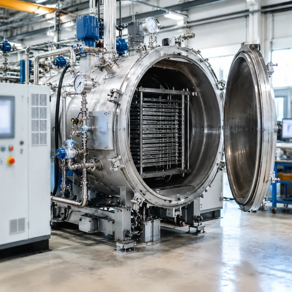
Quench pressure alone does not determine cooling speed. To get the maximum performance out of a vacuum gas quenching pressure of 6, 10, 12, 20, or 25 bar, three core engineering parameters must align: gas medium, flow dynamics, and hot zone construction.
Process Gas Selection: Nitrogen vs. Argon vs. Helium
The gas medium directly changes the convective heat transfer coefficient during the high-pressure gas quenching (HPGQ) cycle. Understanding how gas density and thermal conductivity interact with pressure is essential for mastering heat transfer in a vacuum furnace.
-
- Nitrogen (N2): The industry standard for over 90% of tool steel and high-speed steel hardening. It delivers an optimal balance of cost, safety, and cooling velocity at 10 to 25 bar.
- Argon (Ar): Essential for titanium alloys, superalloys, and specific medical grades where nitrogen pickup or surface nitriding must be completely avoided. Because argon is heavier, it provides lower cooling efficiency than nitrogen at identical pressure levels.
- Helium (He): Provides the highest thermal transfer rate—up to 2.5 times faster than nitrogen at the same bar rating. We use helium for ultra-fast cooling of dense cross-sections, though it requires a dedicated closed-loop recovery system due to gas cost.
| Quench Gas | Relative Cooling Efficiency | Typical Operating Pressure | Primary Application |
|---|---|---|---|
| Nitrogen (N2) | High (Baseline 1.0) | 6 to 25 Bar | Tool steels, die steels, HSS, structural alloys |
| Argon (Ar) | Low (0.6x to 0.7x of N2) | 2 to 10 Bar | Titanium, superalloys, reactive metals |
| Helium (He) | Highest (1.8x to 2.5x of N2) | 10 to 20 Bar | Ultra-thick sections, severe critical cooling rate alloys |
360-Degree Nozzle Rings vs. Alternating Directional Gas Flow
Pressure creates the driving force, but gas velocity vectors dictate distortion control. We utilize targeted flow management systems to keep workpieces within tight dimensional tolerances:
-
- 360-Degree Annular Nozzle Arrays: Fixed, circular nozzle rings distribute high-velocity gas evenly around the entire perimeter of the charge. This setup works best for cylindrical tooling, symmetrical molds, and uniform batch baskets.
- Dynamic Alternating Directional Flow: Computer-controlled flapper valves alternate gas flow between top-to-bottom and side-to-side paths. By reversing the gas direction during the critical 800°C to 500°C transformation window, we eliminate thermal gradient shadowing and prevent part bowing on asymmetrical tooling.
Hot Zone Construction: Graphite Felt vs. All-Metal
The hot zone must withstand cyclic gas blasts at up to 25 bar without shedding insulation or losing thermal uniformity.
-
- Graphite Hot Zone (Graphite Elements & Rigid Carbon Felt): The premier choice for industrial heat treating. It offers high energy efficiency, exceptional thermal shock resistance during 25 bar gas blasts, operating temperatures up to 1300°C–1400°C, and low maintenance overhead.
- All-Metal Hot Zone (Molybdenum & Stainless Steel Shields): Designed for cleanroom, aerospace, and medical specs. While all-metal hot zones demand higher heating power, they eliminate carbon vapor transfer, ensuring zero risk of surface carburization on sensitive alloys.
Master Selection Matrix: Quench Pressure vs. Steel Grade vs. Ruling Section
Choosing the right vacuum gas quenching pressure comes down to matching your alloy's continuous cooling transformation (CCT) curve with the physical thickness of your parts. If the pressure is too low, the cooling velocity drops in the core, leading to unwanted bainite or pearlite transformation. If it is excessively high for simple air-hardening grades, you burn unnecessary electrical blower power and gas volume.
We engineered our vacuum hardening furnace systems with multi-level pressure settings (from 2 up to 25 bar) so heat treaters can calibrate quench severity directly to the workload.
Operating Pressure, Ruling Section, and Oil Equivalency Guide
| Quenching Pressure (Bar) | Typical Steel Grades | Max Ruling Section for Core Hardness | Cooling Benchmark & Oil Quench Equivalency |
|---|---|---|---|
| 6 Bar | AISI D2, A2, 420 Stainless, O1 (thin sheets) | Up to 60 – 80 mm | Slow oil / forced air equivalent. Excellent for zero-distortion requirements on high-alloy air-hardening tooling. |
| 10 – 12 Bar | AISI H13 (1.2344), D2 (heavy blocks), Matrix steels, 1.2379 | Up to 100 – 130 mm | Standard/medium oil equivalent. Delivers uniform convective heat transfer across typical plastic molds and stamping dies. |
| 16 Bar | M2, M35 high-speed steels, heavy H13 die-casting blocks, 1.2714 | Up to 150 – 180 mm | Fast oil equivalent. Ensures rapid cooling across the critical 800°C to 500°C transformation zone to prevent carbide precipitation. |
| 20 – 25 Bar | Powder metallurgy (PM) steels, M42 HSS, low-alloy steels (4140, 8620 LPC carburized) | 200+ mm solid sections | High-speed, accelerated oil quenching equivalent. Achieves full core martensitic transformation without liquid residue. |
Key Engineering Benchmarks for Shop Floor Setup
-
- Ruling Section Limits: For high-hardenability steels like D2 or A2, 6 to 10 bar provides ample cooling velocity even in thick cross-sections. However, when quenching hot-work tooling or high-speed steel tools above 100 mm in diameter, stepping up to 12 to 16 bar is mandatory to maintain specified core toughness.
- Direct Oil Replacement: If your shop processes low-alloy structural steels or deep-case vacuum carburized components, a 20 to 25 bar high-pressure gas quench delivers the heat transfer coefficient required to match rapid oil agitated baths while keeping part surfaces clean, bright, and completely free of post-quench wash requirements.
- Distortion vs. Hardness Balance: Selecting the lowest viable bar rating that still satisfies the critical cooling rate guarantees lower thermal gradients across complex geometry, drastically cutting down post-heat-treat grinding and straightening costs.
Economic and Operational Trade-Offs: CAPEX vs. OPEX in Vacuum Gas Quenching
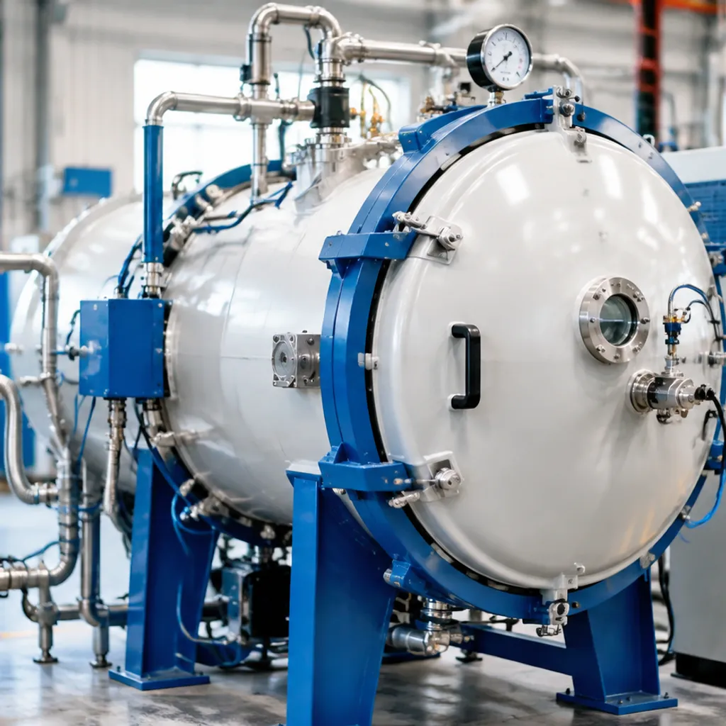
Electrical Blower Power Demands and Transformer Sizing
As operating pressure rises, gas density increases, demanding significantly more mechanical energy to push the gas through the hot zone nozzles and heat exchanger channels:
-
- 6 to 10 Bar Systems: Typically operate with 45 kW to 90 kW blower motors. These configurations place modest demands on factory electrical infrastructure, allowing standard transformer connections without major facility upgrades.
- 12 to 16 Bar Systems: Generally require 90 kW to 132 kW motors. Variable frequency drives (VFDs) manage startup inrush currents and allow tailored cooling ramps.
- 20 to 25 Bar Systems: Demand heavy-duty blower drives ranging from 160 kW to over 250 kW. Integrating these ultra-high-pressure units requires evaluating total substation capacity, peak electrical demand charges, and transformer load limits.
Single-Use Gas Venting vs. Closed-Loop Gas Recovery Systems
Gas consumption per cycle is one of the largest ongoing expenses in high-pressure gas quenching:
-
- Direct Venting (6 to 10 Bar): For standard tool-and-die shops running nitrogen at moderate pressures, venting gas directly to the atmosphere after cooling is often the simplest and most cost-effective path, avoiding the capital cost of recovery skids.
- Closed-Loop Recovery (12 to 25 Bar): Filling a large vacuum chamber to 20 or 25 bar consumes massive volumes of gas per batch. At this scale, or whenever using costly argon gas, an integrated gas recovery system is vital. We pair high-pressure vessels with surge receiver tanks, multi-stage gas booster compressors, and particulate filtration to reclaim up to 85% to 90% of the process gas, providing rapid payback on multi-shift production lines.
Vessel Pressure Certifications and Long-Term Seal Maintenance
Operating at extreme pressure ranges while maintaining deep vacuum levels requires strict mechanical integrity and proactive upkeep:
-
- Regulatory Vessel Compliance: High-pressure vacuum chambers must meet international pressure vessel codes. Our systems are built in alignment with established pressure vessel quality certifications such as ASME Section VIII and CE-PED standards, incorporating calibrated safety relief valves, burst discs, and automated pneumatic chamber locks.
- Seal Reliability Under Cyclic Fatigue: Transitioning from high vacuum ($10^{-2}$ to $10^{-4}$ Pa range) to 20–25 bar positive pressure stresses chamber door seals, sight glasses, and dynamic motor shaft feedthroughs. We utilize reinforced elastomer O-ring profiles, cooled seal flanges, and automated hydraulic clamp rings to prevent micro-leaks, reduce seal wear, and keep maintenance downtime predictable.
Frequently Asked Questions About Vacuum Gas Quenching Pressure
Can 20 to 25 bar gas quenching completely replace oil quenching?
For high-alloy tool steels, high-speed steels (HSS), powder metallurgy grades, and medium-alloy steels, 20 to 25 bar high-pressure gas quenching (HPGQ) matches or exceeds standard oil quench cooling velocities. It eliminates oil residue, post-wash cleaning steps, and disposal costs while keeping parts bright and clean. However, low-hardenability plain carbon steels with extremely short transformation times on the CCT diagram may still require traditional oil quenching or double-chamber vacuum oil quench systems to achieve full core hardness.
How do I determine if 10 bar is sufficient for my tool steel mix?
A 10 bar vacuum gas quenching pressure is the industry workhorse for air-hardening steels. It is fully sufficient if your shop primarily processes:
Alloy grades: AISI D2, H13, A2, S7, and 420-series martensitic stainless steels.
Workpiece sizes: Solid cross-sections and ruling sections under 100 mm.
Production priorities: Lower gas consumption per cycle and minimal thermal distortion on slender tooling.
If your product mix shifts toward massive die-casting blocks exceeding 150 mm or M2/M35 high-speed tooling, stepping up to a 12 to 20 bar system is recommended to guarantee core hardness.
Why does workpiece ruling section dictate minimum quench pressure?
Thick workpieces suffer from the thermal mass effect: heat transfers slowly from the center to the exterior surface. As cross-sectional thickness increases, the surface must be cooled rapidly enough to pull heat out of the core before the center temperature enters the ferritic, pearlitic, or bainitic transformation zones. Raising the gas quench pressure increases gas density and the overall convective heat transfer coefficient, allowing the furnace to extract core heat at the critical cooling rate.
When is helium gas required over nitrogen for high-pressure gas quenching?
Nitrogen ($N_2$) serves as the standard process gas for the vast majority of 6 to 25 bar quenching cycles. Helium ($He$) is selected when:
Critical cooling rates cannot be met by nitrogen alone at maximum vessel pressure ratings.
Processing dense, highly sensitive superalloys or heavy cross-section high-speed tools.
Component geometry demands the highest possible heat transfer coefficient without increasing mechanical gas impingement pressure.
Because helium is an expensive noble gas, we configure systems utilizing helium with closed-loop gas recovery and recycling systems to reclaim up to 95% of the gas volume per cycle.
How does dynamic gas flow direction prevent asymmetric part distortion?
Non-uniform cooling rates across a part create steep thermal gradients, causing thermal stress, asymmetric shrinkage, and cracking. Modern systems resolve this using:
360° annular nozzle rings: High-velocity gas jets surround the workload uniformly from all radial angles.
Alternating dynamic gas flow: Computer-controlled dampers alternate flow between top-to-bottom and bottom-to-top directions.
Controlled gas velocity: Breaking the thermal boundary layer evenly across both thin edges and heavy sections.
Understanding how a vacuum furnace works during high-speed gas circulation enables our team to tailor specific cooling profiles, ensuring your components achieve full hardness while holding strict dimensional tolerances.