Understanding the Role of Backfilling in High Vacuum Brazing
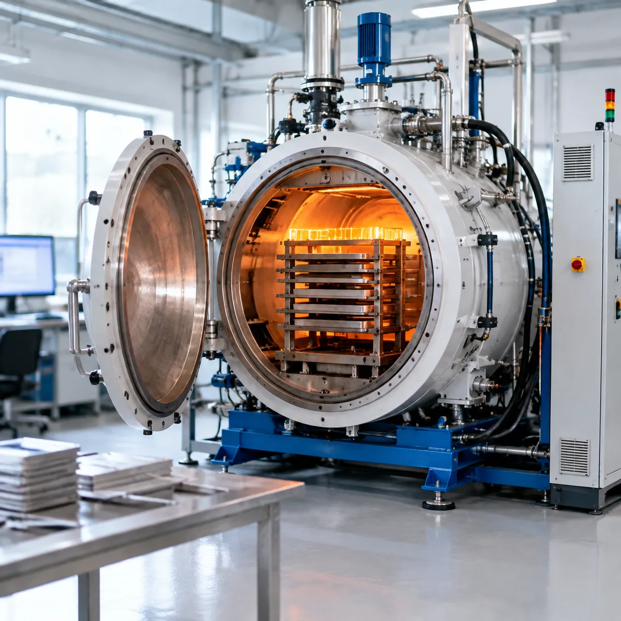
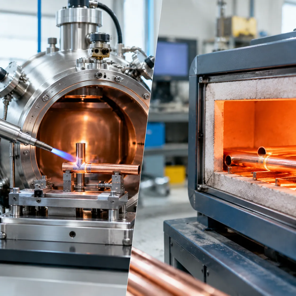
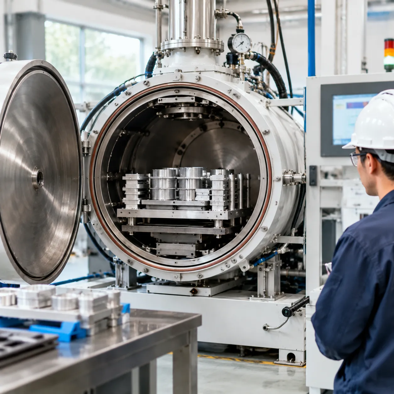
In high-vacuum thermal processing, backfilling is not merely venting a retort—it is a critical thermodynamic tool. Our engineering team approaches backfilling as a dual-purpose control system designed to stabilize active metallurgy at elevated temperatures and execute rapid thermal extraction. Inadequate control over gas purity, introduction timing, or flow kinetics directly causes severe backfill issues on high vacuum brazing furnace systems, leading to scrap-level joint defects, surface discoloration, and structural distortion.
Partial Pressure Backfill vs. Rapid Cooling (Quenching) Backfill
Differentiating between partial pressure stabilization and positive-pressure gas quenching is critical for process reliability:
| Parameter | Partial Pressure Backfill | Rapid Cooling (Quenching) Backfill |
|---|---|---|
| Cycle Phase | Soak and liquidus braze plateau | Post-solidification cooling cycle |
| Target Pressure | 0.5 to 5.0 mbar (0.375 to 3.75 Torr) | 1.5 to 10.0 bar (absolute) |
| Primary Gas | Ultra-high purity (UHP) Argon / Nitrogen | UHP Argon, Nitrogen, or Helium mixtures |
| Primary Objective | Suppress elemental volatilization | Rapid joint freezing and cycle-time reduction |
| Flow Regime | Dynamic micro-flow / continuous sweep | High-velocity recirculating convective flow |
Vacuum / Pressure Level
High Vacuum: < 10⁻⁴ mbar
↓
Partial Pressure Plateau: 0.5–5.0 mbar → Suppresses Alloy Boil-Off
↓
Overpressure Gas Quenching: 1.5–10 bar → Convective Microstructure Freezing
Suppressing High-Vapor-Pressure Braze Alloy Vaporization (Ag, Cu, Mn, Zn)
At elevated brazing temperatures, elements with low thermodynamic stability and high vapor pressures rapidly sublime in deep vacuum (< 10⁻⁴ mbar). This elemental boil-off alters filler alloy chemistry, shifts the liquidus/solidus window, and deposits conductive metallic films onto furnace cold walls, heating elements, and ceramic isolators.
-
- Silver (Ag) & Copper (Cu): Susceptible to volatilization above 950°C in sub-micron vacuum.
- Manganese (Mn) & Zinc (Zn): Highly volatile; boil-off occurs below standard active brazing ranges without an inert partial pressure barrier.
- Mechanism: Introducing continuous ultra-pure inert gas shortens the mean free path of vaporized atoms, forcing them back into the melt pool through localized molecular collision.
Accelerated Convective Cooling Dynamics to Freeze Joints and Shorten Cycle Times
Once the braze alloy solidifies, radiative heat transfer loses efficiency exponentially as the temperature drops below 600°C.
-
- Transition to Convective Heat Transfer: We inject pressurized inert gas to shift the heat rejection mechanism from radiation ($q \propto T^4$) to forced convection ($q = h A \Delta T$).
- Microstructure Freezing: Rapid gas quenching accelerates cooling through critical precipitation zones, locking in fine-grained microstructures and preventing brittle intermetallic compound (IMC) coarsening along the braze interface.
- Cycle Optimization: High-velocity overpressure cooling slashes turnaround time, boosting overall furnace throughput without sacrificing part integrity.
Physics of the Vacuum-to-Pressure Transition: Pressure Differentials and Gas Turbulence
Switching a furnace environment from molecular flow (< 10⁻³ mbar) to turbulent viscous flow (> 1 bar) creates severe transient mechanical stresses inside the hot zone:
-
- Flow Regime Shock: Gas shifting rapidly from molecular drift to continuum flow generates high kinetic energy impact zones.
- Localized Pressure Imbalances: Uncontrolled mass flow spikes create instantaneous differential pressures ($\Delta P$) across thin-walled assemblies, causing part shifting, honeycomb core crushing, or brazing jig misalignment.
- Aerosolized Particulates: Unregulated turbulence re-entrains loose graphite dust, metal condensates, and insulation fibers, redistributing contaminants directly onto molten or solidifying braze fillets.
Common Symptoms of Backfill Malfunctions in Vacuum Brazing
Post-Brazing Oxidation and Discoloration (Straw, Blue, and Matte-Gray Defects)
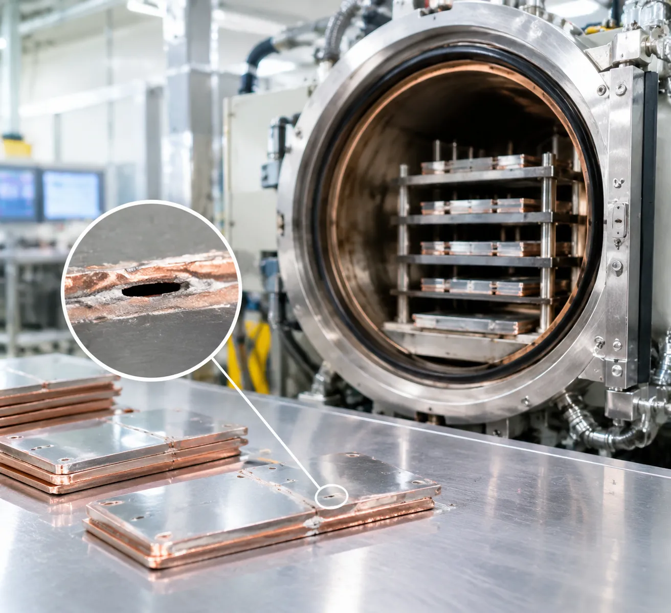
Discoloration on finished assemblies is the most frequent red flag during vacuum brazing contamination troubleshooting. In a clean run, parts exit bright and metallic. Surface discoloration tells a specific story about when and how oxygen or moisture entered the chamber:
Light Straw to Gold Tint: Indicates minor trace contamination or backfill gas with an inadequate dew point entering at temperatures between 200°C and 400°C.
Blue to Deep Purple Scale: Points to severe air ingress or high-temperature moisture exposure above 500°C, typically caused by premature gas admission or contaminated argon supplies.
Matte-Gray or Black Soot: Caused by hydrocarbon contamination or severe moisture reactions that fully oxidize base alloys and prevent clean braze formation. Following a disciplined vacuum furnace brazing cycle guide and process parameters is critical to matching backfill temperatures with base metal chemistry.
| Visual Symptom | Temperature Window | Primary Root Mechanism |
|---|---|---|
| Straw / Golden | 200°C–400°C | Trace O₂ / moisture in cooling gas |
| Deep Blue / Purple | 400°C–650°C | Gross air leak / wet backfill line |
| Matte Gray / Black | > 650°C (Near Solidus) | High-temperature O₂ ingress / oil fouling |
Braze Joint Porosity, Incomplete Wetting, and Alloy Depletion
Improper inert gas management during the critical melt and freeze stages ruins joint integrity:
Porosity and Voids: Trapped gas pockets form when the partial pressure backfill fluctuates during capillary flow.
Incomplete Wetting and Meniscus Pullback: Surface oxides forming during gas introduction increase surface tension, stopping the braze filler from flowing smoothly along the joint interface.
Element Volatilization (Alloy Depletion): Failing to establish a stable partial pressure backfill before reaching liquidus temperatures causes volatile elements like silver, copper, or manganese to vaporize, leaving starved, brittle braze joints.
Part Shifting, Assembly Distortion, and Hot Zone Thermal Shock Cracking
Unregulated gas entry during high-rate cooling creates mechanical and thermal havoc inside the chamber:
Blast Shifting: High-velocity, un-diffused gas blasts physically dislodge delicate components and misalign precision fixturing before filler metal fully solidifies.
Component Warpage: Non-uniform gas injection creates sharp thermal gradients across complex geometries, driving uneven contraction and dimensional distortion.
Hot Zone Thermal Shock: Sudden cold gas exposure against graphite or molybdenum heating elements and ceramic isolators leads to element cracking, insulation spalling, and shortened hot zone life.
Uncontrolled Pressure Surges, Vacuum Gauge Spikes, and Pump Fault Trips
Backfill sequence failures also disrupt the vacuum pumping system and control instrumentation:
Gauge Over-Pressure Spikes: Rapid pressure surges can peg and damage delicate wide-range Penning or Pirani vacuum gauges.
Mechanical Pump Faults: Opening backfill valves without isolating high-vacuum diffusion or turbomolecular pumps triggers severe over-pressure interlock trips and risks catastrophic backstreaming into the chamber.
Regulator Hunting: Oscillating chamber pressure readings signal that proportional control valves or backpressure regulators are miscalibrated or fouled by particulates.
Root Causes of Engineering Failures in Backfill Systems
When diagnosing persistent backfill issues on high vacuum brazing furnace setups, we typically find the culprit in mechanical degradation, control timing faults, or gas delivery compromises. Below are the primary engineering failure modes we encounter on the shop floor.
| Failure Mode | Primary Issue |
|---|---|
| 1. Gas Supply Quality | Moisture / Dew Point Decay |
| 2. Actuation Timing | PLC Latency & Valve Sticking |
| 3. Pump Crossover | Oil Backstreaming Migration |
| 4. Nozzle Geometry | Uneven Flow & Plume Choking |
Gas Supply and Line Integrity Issues (Dew Point Degradation and Contamination)
Inert gas backfill lines often suffer from hidden contamination before the gas even reaches the hot zone:
-
- Elevated Dew Point: High vacuum brazing requires an argon gas dew point of -65°C to -70°C (-85°F to -94°F) or drier. A degraded bulk tank vaporizer or saturated line filter raises moisture levels, triggering immediate braze alloy oxidation.
- Permeation Through Flexible Lines: Using rubber or standard elastomer hoses introduces moisture and oxygen permeation. We mandate rigid, orbital-welded stainless steel tubing or high-integrity flex lines with metal seals.
- Stagnant Delivery Legs: Infrequently used manifold sections trap ambient air and outgassed moisture. Without adequate pre-purge cycles, this trapped volume dumps directly into the retort during initial gas admission.
Valve Actuation Latency, Sticking Actuators, and Pneumatic Sequencing Faults
Precise valve coordination prevents dangerous pressure surges and system contamination:
-
- Pneumatic Actuator Wear: Sluggish solenoid response or worn cylinder seals create a timing delay between the gas inlet valve opening and the vacuum isolation valves closing.
- PLC Sequencing Lags: If the high vacuum valve (diffusion or turbomolecular gate) stays cracked open even milliseconds after high-pressure gas injection begins, catastrophic back-pressure waves damage the high-vacuum stack.
- Seat Deterioration: Viton or metallic valve seats exposed to thermal cycling develop micro-leaks, bleeding trace gas or atmospheric air during deep vacuum dwell stages.
Hydrocarbon Backstreaming from Mechanical Roughing Pumps During Transition States
During the vacuum-to-pressure crossover, incorrect pump isolation allows mechanical pump oil vapor to migrate into the hot zone:
-
- Molecular Drag Breakdown: Between 10 and 100 microns (0.01 to 0.13 mbar), gas flow transitions through the molecular slip regime, enabling pump oil molecules to travel upstream against weak gas currents.
- Missing or Saturated Foreline Traps: Failed liquid nitrogen cold traps, exhausted molecular sieve filters, or defective foreline isolation valves fail to block volatile hydrocarbons.
- Premature Roughing Line Venting: Venting or switching valves before fully sealing isolation lines creates a sudden pressure differential that draws oil mist straight into the brazing chamber.
Gas Injection Geometry, Clogged Nozzles, and Asymmetrical Flow Turbulence
Uniform gas distribution protects joint integrity and prevents structural displacement across the load:
-
- Graphite Nozzle Clogging: Soot, binder residue, and braze flux condensate gradually plug 360-degree gas distribution nozzles, choking cooling gas velocity.
- Asymmetrical Jet Plumes: Unequal nozzle discharge velocities generate localized thermal gradients across complex assemblies, causing severe part warpage and cracked joints. Our team addresses these flow imbalances through specialized custom design and engineering services that optimize plenum geometry and gas manifold delivery paths.
- High-Velocity Blast Shifting: High-pressure gas streams directed straight at lightweight braze assemblies blow molten filler metal out of capillary gaps before it solidifies.
Step-by-Step Diagnostic & Troubleshooting Methodology
In-Line Gas Purity and Optical Dew Point Moisture Verification
Never assume process gas arriving at the hot zone is as pure as the certificate on the bulk tank claims. Contamination routinely enters between the supply pad and the furnace inlet.
-
- Install an in-line chilled-mirror optical dew point hygrometer directly at the furnace backfill inlet manifold, not upstream at the bulk tank.
- Sample gas at operating delivery pressure: Ensure moisture levels read at or below -65°C (-85°F) dew point (less than 5 ppmv moisture) for high-purity argon and nitrogen backfill.
- Verify oxygen levels: Utilize a trace zirconia oxygen analyzer. Incoming O2 must remain below 1 ppm for reactive braze alloys. Any moisture or O2 surge during valve opening indicates saturated gas lines or failing supply regulator diaphragms.
Helium Mass Spectrometer Leak Detection Protocol on Manifolds and Seals
Atmospheric air pulling into sub-atmospheric delivery lines during partial pressure backfill is a major cause of braze joint oxidation. We isolate leaks using a helium mass spectrometer leak detector (MSLD) running in sniffing and vacuum modes.
-
- Test backfill lines under positive pressure (Sniffer Mode): Charge the manifold with a 90/10 nitrogen-helium tracer mix at 2 to 3 bar. Sweep all compression fittings, isolation valves, and regulator stems with the probe.
- Test backfill valves under vacuum (Direct Hard Vacuum Mode): Connect the MSLD directly to the furnace roughing port. Evacuate the chamber below 10⁻² mbar, spray helium around backfill solenoid seats, injection poppet shaft seals, and manifold flanges.
- Check actuation shaft packings: Rapidly cycle pneumatic valves while spraying helium at the actuator interface to detect transient leaks across worn O-rings.
PLC Sequence, Interlock Timing, and Crossover Pressure Audits
Erratic backfilling often stems from timing glitches hidden in PLC logic and out-of-spec pressure transducers. We inspect modern single-chamber vacuum furnace with high-pressure gas quenching platforms using a digital oscilloscope or high-speed PLC data logger.
| Audit Parameter | Target Operating Window | Diagnostic Failure Trigger |
|---|---|---|
| High Vacuum Valve Closure | Fully seated before gas injects | Backfill starts with poppet valve cracked > 50 ms |
| Crossover Setpoint Timing | 1.0 to 1.5 second settling dwell | Gas introduction during active diffusion pump draft |
| Roughing Isolation Interlock | Roughing line isolated before purge | Mechanical pump oil pulled into chamber |
| Transducer Response Rate | < 100 ms step response | Capacitance manometer drift causing late shutoff |
Audit the differential pressure transducer calibration every 6 months to guarantee that the switchover from molecular flow to viscous flow does not shock the hot zone or cause severe pressure spikes.
Vacuum Rise Rate and Outgassing Characterization (Leak-Up Rate Testing)
Distinguishing between a real atmospheric leak and virtual outgassing is vital for solving backfill issues on high vacuum brazing furnace lines. We run a standard leak-up rate test:
- Standard Test Cycle: Pump the empty, clean furnace down to base pressure (< 5 × 10⁻⁵ mbar). Close the high-vacuum poppet valve, isolate the roughing circuit, and log the chamber pressure rise every 15 minutes over a 60-minute duration.
- Evaluating Results:
- True Mechanical Leak: The rate-of-rise curve is strictly linear. Pressure continues to climb steadily past 1 mbar. Focus maintenance on valve seats, door seals, and injection manifolds.
- Virtual Outgassing / Moisture: The rate-of-rise curve flattens over time (degressive curve), leveling off as vapor equilibrium is reached. Run an extended hot-zone bakeout cycle to strip absorbed water from graphite insulation or molybdenum shields.
- Pass/Fail Criteria: A healthy, production-ready vacuum brazing chamber must hold a leak-up rate below 5 microns per hour (0.0067 mbar/h) when cold and dry.
Corrective Measures and Preventive Engineering Best Practices
Resolving chronic backfill issues on high vacuum brazing furnace systems requires eliminating contamination vectors, upgrading valve dynamics, and maintaining tight physical control over the hot zone environment. We apply these field-proven engineering standards to stabilize brazing cycles and protect sensitive assemblies.
Upgrading Gas Delivery Infrastructure: Heated Getters and Orbital-Welded 316L Lines
Threaded pipe joints, copper lines, and standard compression fittings gradually allow atmospheric moisture and oxygen permeation. To ensure ultra-pure inert gas reaches the furnace chamber:
-
- Orbital-Welded 316L Stainless Steel Tubing: Replace threaded or flexible rubber lines with electropolished, orbital-welded 316L tubing from the gas manifold to the furnace inlet.
- Point-of-Use Heated Getters: For titanium, nickel superalloys, and active metal braze runs, install point-of-use heated catalytic getters to pull residual oxygen, moisture, carbon monoxide, and hydrocarbons down to sub-ppb (parts per billion) levels.
- In-Line Coalescing & Particulate Filters: Place 0.003-micron metal filters directly upstream of the injection manifold to catch particulate shed from regulators and cryogenic dewar boil-off.
Implementing Multi-Stage Soft-Start Backfill Controls and Proportional Valves
Direct blast gas entry can dislodge precision-fixtured parts and cause rapid thermal stress across delicate graphite or molybdenum heating elements.
-
- Two-Stage Pressure Equalization: We install a bypass loop with an electro-pneumatic proportional metering valve. The system introduces inert gas slowly until chamber pressure rises above 100 mbar, equalizing pressure differentials before opening high-volume main valves.
- Controlled Ramp Dynamics: Soft-start staging prevents violent gas turbulence, eliminating joint misalignment and mechanical shock on heating elements during the initial transition in a high-performance gas quench vacuum furnace.
Closed-Loop PID Partial Pressure Controls with Capacitance Manometers
Thermal conductivity gauges (Pirani or thermocouple gauges) change calibration depending on gas composition. For accurate partial pressure suppression of volatile elements like silver, copper, or manganese:
-
- Capacitance Diaphragm Manometers: Use ambient-temperature or heated capacitance manometers that measure absolute mechanical force independent of gas species.
- Modulated PID Mass Flow Controllers (MFC): Pair the manometer with high-speed mass flow controllers and a dedicated PID loop on the PLC. This maintains exact partial pressure (typically 1 to 5 mbar) throughout the braze melt phase, preventing alloy volatilization while minimizing gas consumption.
Hot Zone Maintenance, De-bind Burnout Cycles, and Injector Re-alignment
Contaminants accumulating inside the insulation pack directly compromise backfill gas quality during heating and cooling cycles.
-
- Periodic High-Temperature Burnout Runs: Schedule routine dry-run bake-out cycles at least 50°C above your standard operating temperature under deep vacuum to strip out binder residues, volatile condensates, and absorbed moisture from graphite felt or metallic radiation shields.
- Injector Nozzle Calibration: Inspect radial 360-degree gas distribution nozzles during every preventive maintenance window. Clean out condensed metallic deposits, replace warped nozzles, and ensure symmetrical flow geometry across all workload tiers to eliminate localized cooling hot-spots.
Vacuum Brazing Backfill Troubleshooting Checklist & Field Action Matrix

Quick-Reference Matrix: Symptom to Root Cause to Field Fix
| Observed Symptom | Primary Root Cause | Corrective Field Action |
|---|---|---|
| Discolored / Oxidized Parts (Blue, Straw, Gray) | Atmospheric air ingress or moisture in gas supply | Check inlet gas dew point (must be \le -60 °C); perform helium leak detection on backfill line solenoid valves and regulator seals. |
| Volatilization / Alloy Boil-Off (Ag, Cu, Mn) | Backfill introduced too late or partial pressure set too low | Adjust PLC cycle sequencing to inject inert partial pressure gas prior to alloy melt stage; verify pressure sensor calibration. |
| Part Distortion & Workpiece Movement | High initial gas blast velocity from unthrottled injection | Reconfigure multi-stage soft-start valve timing; adjust gas distribution nozzles to prevent direct high-velocity impingement on delicate assemblies. |
| Oil Vapor / Hydrocarbon Contamination | Backstreaming during vacuum-to-pressure crossover | Inspect roughing line anti-suckback valves; verify high-vacuum isolation valve closes completely before backfill gas injection begins. |
| Erratic Vacuum Spikes / Slow Quenching | Clogged gas distribution ring or sticking pilot valves | Disassemble and clean carbon soot from gas injection nozzles; service pneumatic actuators and calibrate differential pressure transducers. |
Baseline Leak-Up Rates and Safe Operating Pressure Windows
Maintaining process integrity in a high-performance vacuum brazing furnace requires tight adherence to baseline pressure limits and leak-rate thresholds:
- Acceptable Hot Zone Leak-Up Rate: Must not exceed 5 microns per hour (0.0067 mbar/h) in a clean, outgassed, and empty chamber under ambient conditions.
- Inlet Gas Purity Standards:
- Industrial High-Purity Argon: \ge 99.999% (Grade 5.0) purity with a dew point of -65 °C or drier.
- Nitrogen (compatible non-reactive alloys only): \ge 99.999% purity, moisture levels \le 2 ppm.
- Safe Partial Pressure Backfill Windows: Maintain between 0.5 mbar and 3.0 mbar (375 to 2250 microns) of inert gas during active heating to suppress alloy element vaporization without degrading thermal insulation performance.
- Rapid Cooling Quench Pressures: Set pressure thresholds between 0.9 bar and 2.0 bar (absolute) for standard convective gas quenching cycles to balance joint freezing velocity and structural fixture stability.
Frequently Asked Questions (FAQs) About Vacuum Brazing Backfill Issues
Why does stainless steel turn blue or straw-colored right after nitrogen backfill?
Surface discoloration on stainless steel—ranging from a light straw tint to deep blue or matte gray—points to high-temperature oxidation or nitriding during the cooling stage. This defect typically occurs due to two root causes:
High backfill introduction temperature: Introducing nitrogen or an inert cooling gas while the furnace hot zone is still above safe threshold temperatures (typically above 200°C / 400°F for sensitive alloys) accelerates chemical reactions between trace oxygen and chromium.
Gas supply contamination: Trace oxygen or moisture in the nitrogen gas stream reacts instantly with hot metal surfaces, forming thin oxide interference layers.
What minimum gas purity and dew point standards are required to prevent oxidation?
To eliminate oxidation and maintain bright, clean braze assemblies, we enforce strict gas quality standards at the point of entry to the furnace chamber:
Gas Purity: Minimum 99.999% (Grade 5.0) purity for argon or nitrogen; Grade 5.5 (99.9995%) is recommended for active elements or titanium-stabilized alloys.
Dew Point Level: The gas dew point measured directly at the furnace backfill inlet must be -65°C (-85°F) or lower (representing less than 5 ppm moisture).
Routine monitoring using calibrated optical chilled-mirror hygrometers ensures delivery lines do not degrade over time, as outlined in our vacuum furnace calibration guide.
How do I stop braze alloy boil-off before convective cooling backfill begins?
Alloy element volatilization (such as silver, copper, manganese, or zinc depletion) occurs when the chamber vacuum level drops below the vapor pressure of the constituent metals at liquidus temperatures.
To halt boil-off:
1. Engage Partial Pressure Control: Inject a controlled micro-flow of high-purity argon or nitrogen to maintain chamber pressure between 0.5 mbar and 3.0 mbar (375 to 2,250 microns) just before reaching the braze alloy liquidus point.
2. Synchronize Thermal Hold Cycles: Stabilize furnace temperature under partial pressure to allow full capillary action and wetting without vaporizing low-boiling-point alloy elements before firing the high-velocity cooling gas quench.
Reviewing the fundamentals in our vacuum furnace working guide helps balance thermal ramp rates and partial pressure timing to prevent alloy loss.
What triggers roughing pump oil backstreaming during vacuum-to-pressure transitions?
Hydrocarbon backstreaming occurs when the system operates in the molecular flow transition zone (typically between 10 and 100 microns / 0.013 to 0.13 mbar) without sufficient forward gas velocity to sweep oil molecules back into the pump.
Key triggers include:
Improper Valve Sequencing: Opening roughing or backing lines while the chamber is at a deeper vacuum than the foreline without an active gas purge.
Lack of Continuous Gas Ballast: Running mechanical pumps under dead-head conditions during the hold prior to backfilling, allowing oil vapors to migrate upstream into the hot zone.
Saturated Foreline Traps: Depleted molecular sieve traps or failed cold traps that allow oil vapor migration during transition cycles.
How often should vacuum furnace backfill manifolds undergo helium leak testing?
We recommend executing a dedicated helium mass spectrometer leak test on all gas delivery manifolds, solenoid valves, and check valves under the following schedule:
Semi-Annually: As part of standard preventive maintenance to inspect high-cycling pneumatic seats, O-rings, and compression fittings.
Post-Maintenance: Immediately following any line modifications, regulator replacements, or hot zone overhauls.
Upon Leak-Up Rate Spikes: Whenever the baseline furnace leak-up rate exceeds 5 microns (0.0067 mbar) per hour, pinpointing whether the leak originates inside the vessel or along the pressurized backfill gas manifold.