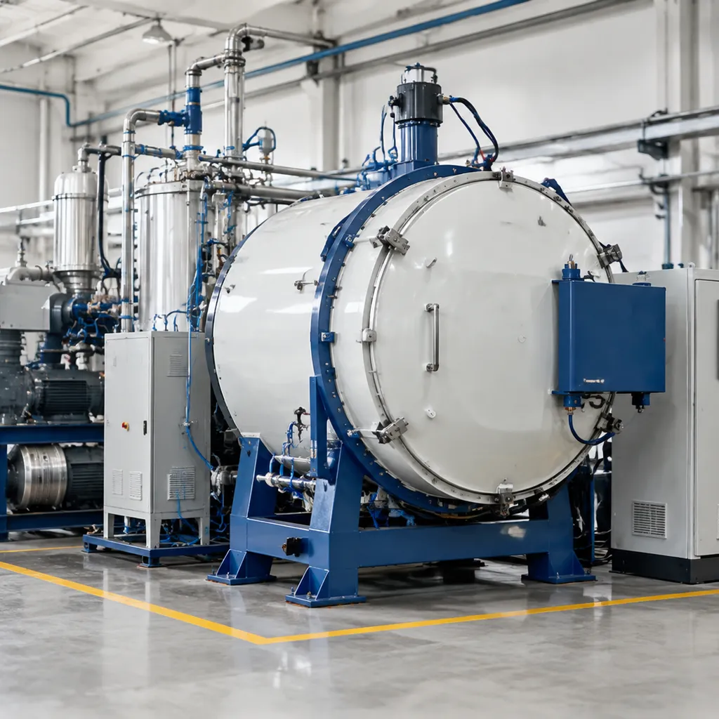
Formula details
Product Details
Overview
Product Overview and Core Benefits
What Is a Low-Pressure Carburizing Vacuum Furnace?
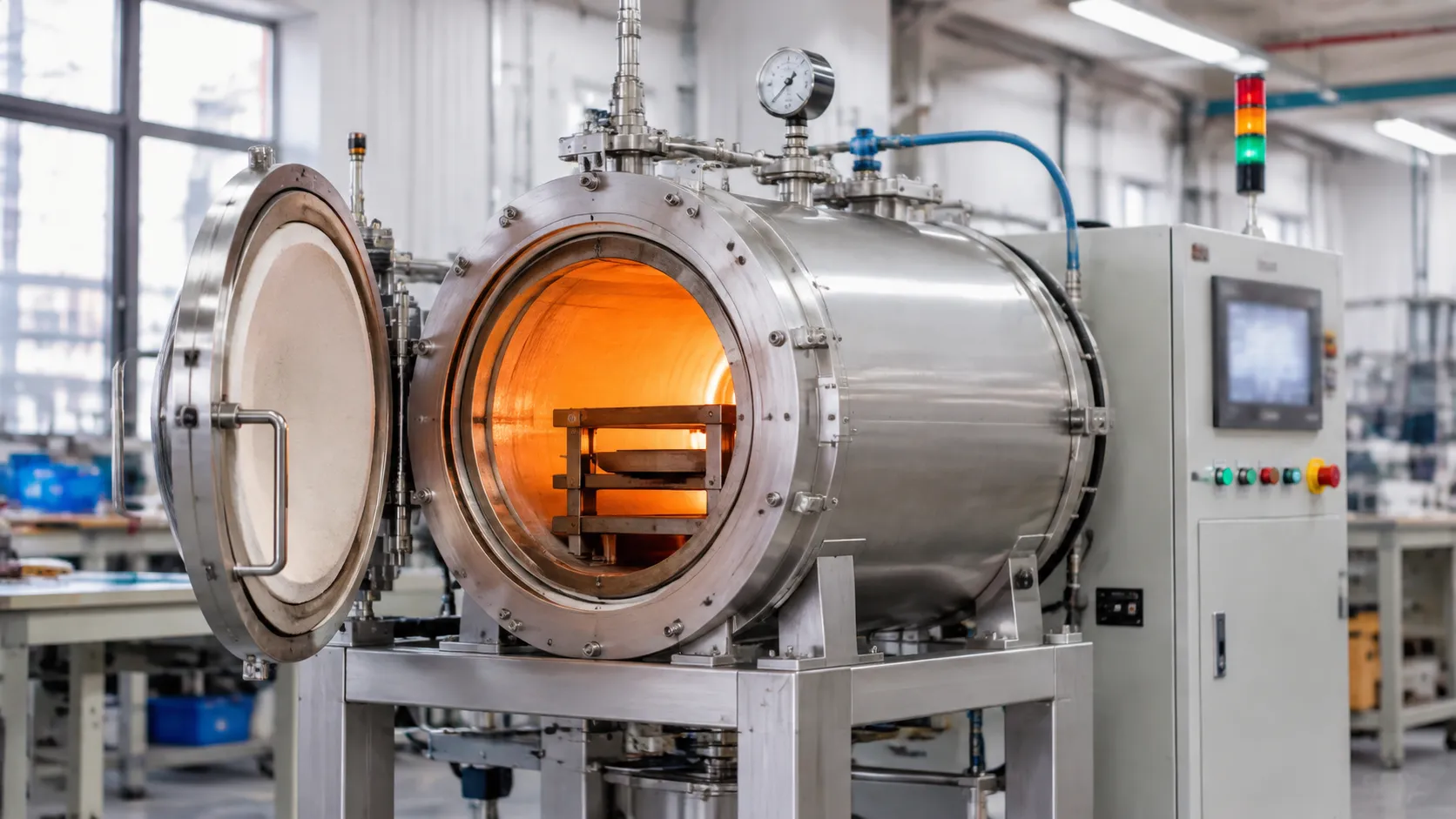
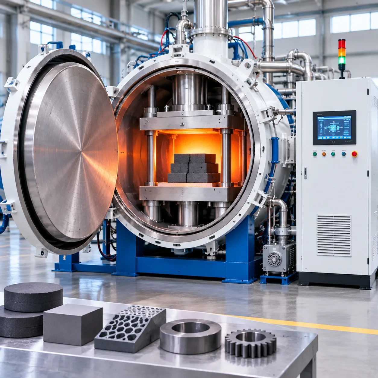
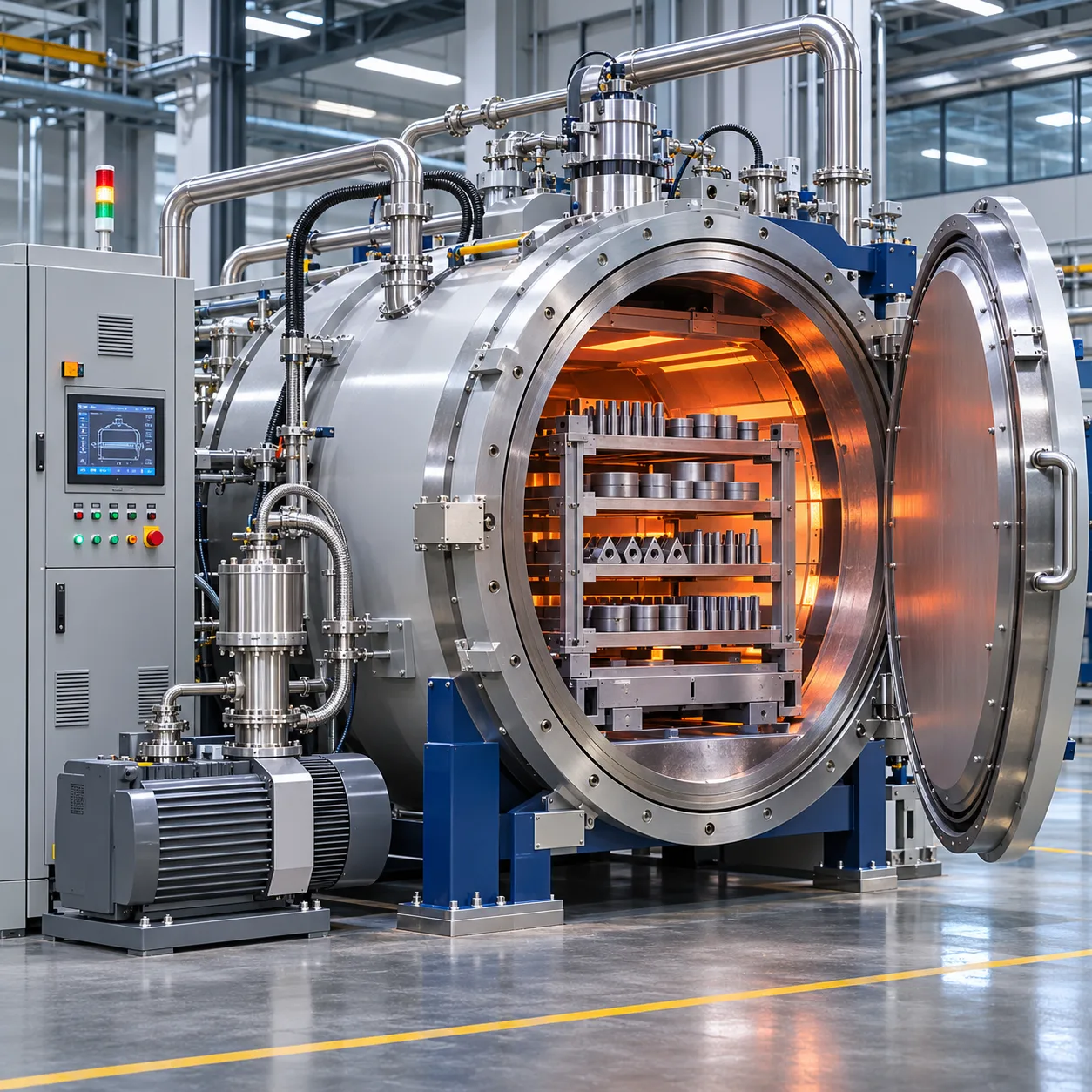
A low-pressure carburizing vacuum furnace (LPC vacuum furnace) is an advanced thermal processing system designed for precision surface case-hardening under deep vacuum and controlled sub-atmospheric pressures. By replacing traditional endothermic atmospheres with pulsed hydrocarbon gas injection inside a sealed vacuum hot zone, our systems deliver precise carbon penetration, eliminate intergranular oxidation (IGO), and minimize part distortion across complex geometries.
Vacuum Heating
Oxygen-Free Environment
↓
Hydrocarbon Injection
Boost Phase, 2–10 mbar
↓
Carbon Diffusion
Controlled to Target Case Depth
↓
High-Pressure Gas Quenching
Oil-Free Hardening
Core Engineering Process
Our low-pressure carburizing equipment integrates four coordinated process phases to ensure metallurgical repeatability:
-
- Vacuum Heating: Workloads are brought to carburizing temperatures (typically 880°C to 1050°C) under high vacuum, degassing surfaces and ensuring uniform cross-sectional thermal distribution.
- Hydrocarbon Injection (Boost Phase): High-purity hydrocarbon gas (such as acetylene, C_2H_2) is pulsed into the hot zone at low pressures (2 to 10 mbar). The gas cracks directly on the catalytic steel surface for rapid, uniform carbon absorption.
- Carbon Diffusion (Diffuse Phase): Gas flow stops while parts remain under vacuum at elevated temperatures, allowing absorbed carbon to diffuse inward to meet precise case-depth profiles.
- Controlled Quenching: An integrated high-pressure gas quenching (HPGQ) system uses nitrogen (N_2) or helium (He) up to 20 bar to harden parts without liquid quench oils.
Key Advantages Over Conventional Methods
| Performance Factor | Conventional Atmosphere Carburizing | Low-Pressure Carburizing Vacuum Furnace |
|---|---|---|
| Intergranular Oxidation (IGO) | Common (10–25 μm depth, requires grinding) | Zero IGO (completely oxygen-free environment) |
| Case-Depth Uniformity | Uneven on root profiles and blind holes | ± 0.05 mm variance across complex geometries |
| Part Distortion | High (thermal gradients and oil turbulence) | Minimized distortion via adjustable gas nozzle velocity |
| Carburizing Temperature | Typically limited to 930 °C | High-temperature capable (up to 1050 °C for faster cycles) |
| Process Control | Atmosphere potential (Cₚ) calculations | Direct mass-flow pulsed recipe management |
Environmental and Operational Benefits
-
- Clean, Ready-to-Use Parts: Components emerge dry, bright, and soot-free, removing post-quench washing and degreasing steps.
- Zero Hazardous Quench Oils: Integrated gas quenching eliminates industrial quench oils, fire hazards, and hazardous chemical disposal.
- Minimal Gas Consumption: Pulsed low-pressure injection consumes a fraction of the gas volume required by conventional endothermic generators.
- Lower Carbon Footprint: Direct electrical vacuum heating and reduced cycle times cut overall kilowatt-hour consumption per ton of treated material.
Key Features and Engineering Advantages
Heavy-Duty Vacuum Chamber and Thermal Insulation
-
- Double-Wall Water-Cooled Vessel: Heavy-gauge carbon steel or stainless steel construction engineered for high vacuum levels and rapid gas quenching cycles.
- Low-Loss Hot Zone: High-purity rigid graphite felt or metallic molybdenum radiation shields that minimize power consumption and ensure rapid thermal response.
- Graphite Heating Elements: Low-mass curved graphite elements placed 360 degrees around the work zone to eliminate cold spots.
Pulsed Low-Pressure Carburizing System
We use dynamic mass flow controllers (MFC) to regulate sub-atmospheric hydrocarbon injection (typically high-purity acetylene). The system operates through precision boost-diffuse cycles:
Micro-Pulse Gas Dosing: Injects precise amounts of process gas at pressures between 1 mbar and 10 mbar, preventing soot formation.
Deep Feature Penetration: Evenly delivers carbon to complex geometries, root fillets of gears, and small blind holes.
Automated Diffusion Control: Balances carbon potential across cycles to hit exact surface carbon targets and case depths.
Integrated High-Pressure Gas Quenching (HPGQ)
For operations requiring oil-free, clean heat treatment, our furnace architecture integrates advanced gas cooling systems. Similar to our single-chamber vacuum furnace with high-pressure gas quenching, this setup uses high-flow radial nozzles and high-efficiency gas-to-water heat exchangers.
Pressure Range: Quench pressure adjustable up to 20 bar using nitrogen (N₂) or helium (He).
Distortion Management: Variable-speed, frequency-controlled blower motors and reversible gas-flow directions help minimize component distortion.
Multi-Zone Temperature Control and Uniformity
-
- Multi-Zone Trim Control: Independent power regulation across multiple heating zones guarantees compliance with AMS 2750 and CQI-9 pyrometry standards (± 5 °C or tighter).
- Thermocouple Setup: Type S/R control and over-temperature thermocouples backed by dedicated workload monitoring ports.
| Engineering Subsystem | Standard Specification | Operational Benefit |
|---|---|---|
| Carburizing Method | Pulsed acetylene (C₂H₂) at 1–10 mbar | Low-soot operation and uniform carburizing of complex geometries and deep holes |
| Quench Capabilities | Gas quenching up to 20 bar (N₂ / He) | Clean parts, no post-quench washing, reduced distortion |
| Thermal Uniformity | ±5°C, Class 2 hot zone | Consistent core hardness and case-depth profile |
| Vacuum System | Rotary vane / dry screw pump + Roots booster | Rapid pump-down and low ultimate pressure |
| Automation | Industrial PLC + SCADA / touchscreen HMI | Supports batch traceability and CQI-9 / AMS 2750 compliance documentation |
Vacuum Regulation and Process Safety Interlocks
-
- Pumping System: Combination of multi-stage mechanical booster pumps and rotary vane (or dry screw) roughing pumps for fast evacuation.
- Pressure Management: Closed-loop capacitance manometers control sub-atmospheric vacuum levels during carburizing.
- Safety Automation: Multi-tier hardware and software interlocks protect against over-temperature, loss of water flow, improper chamber sealing, and over-pressure events.
Automated PLC Controls and Recipe Storage
-
- Touchscreen HMI Interface: Real-time cycle tracking, graphical process trends, and one-touch recipe selection.
- Data Traceability: Automated logging of temperature curves, vacuum levels, gas flows, and quench pressures for strict audit compliance.
- Simulation Software: Integrated carbon profile calculators to accurately predict case depth and optimize boost-diffusion timing before running batches.
Modular Layout and Custom Configurations
We build these systems to fit your floor plan and workflow:
Single-Chamber Units: Compact footprint optimized for flexible batch production and quick recipe changeovers.
Multi-Chamber Systems: Continuous multi-cell designs where separate heating, carburizing, and quenching modules maximize throughput.
Low-Pressure Carburizing Vacuum Furnace Technical Specifications
We design and configure each low-pressure carburizing vacuum furnace to deliver tight metallurgical repeatability across varying production loads. The table below outlines standard configurations, baseline process capabilities, and utility requirements.
| Parameter / Feature | Standard Specification Range | Heavy-Duty / High-Capacity Option |
|---|---|---|
| Working Zone Dimensions (W × H × L) | 400 × 400 × 600 mm to 600 × 600 × 900 mm | 800 × 800 × 1200 mm to 1200 × 1000 × 1500 mm |
| Max Workload Capacity (Gross) | 300–800 kg | 1,000–2,500 kg |
| Maximum Operating Temperature | 1050°C (1922°F) | Up to 1250°C (2282°F) |
| Temperature Uniformity | ±5°C (±9°F), AMS 2750G Class 2 | ±3°C (±5°F) for critical aerospace applications |
| Carburizing Process Gases | Acetylene (C₂H₂), cyclohexane, propane | Multi-gas switching (C₂H₂ / N₂ / NH₃ for carbonitriding) |
| Operating Carburizing Pressure | 2–10 mbar (1.5–7.5 Torr) | Dynamic pulsed injection (1–15 mbar) |
| High-Pressure Gas Quenching (HPGQ) | 2–10 bar absolute (N₂) | Up to 20 bar absolute (N₂ or He) |
| Ultimate Vacuum Level | < 1 × 10⁻² mbar (roughing) / < 5 × 10⁻⁴ mbar (high vacuum) | High-vacuum turbomolecular pump packages available |
| Chamber Leak Rate | < 0.001 mbar·L/s | Ultra-tight vacuum seal validation |
| Cooling Method / Direction | Reversible 360° radial or top-to-bottom gas flow | Alternating directional nozzle grids |
Thermal Performance and Uniformity
Our heating chambers use high-purity graphite or metallic hot zones insulated with rigid graphite board and CFC (carbon-fiber composite) fixtures to maximize thermal efficiency:
-
- Heating Elements: Curved graphite or molybdenum heating segments provide balanced, multi-zone radiation around the entire workload footprint.
- Ramp Rates: Rapid heating from ambient to 950 °C at up to 15 °C/min under vacuum, shortening overall floor-to-floor cycle times.
- Thermal Survey Compliance: Verified multi-point temperature uniformity tested to CQI-9 pyrometry and AMS 2750 standards across empty and fully loaded charges.
Process Gas Delivery and Pressure Management
Precision gas dosing is critical for stable carbon mass transfer without free soot formation:
- Pulsed Dosing System: Fast-acting digital mass flow controllers (MFCs) inject high-purity acetylene (C₂H₂) during boost phases, interspersed with controlled vacuum diffusion stages.
- Pressure Control: Automated throttle valves maintain chamber pressure between 2 and 8 mbar during injection to support gas penetration into blind holes, narrow gear roots, and dense load arrays.
- Purge & Neutral Atmosphere: Integrated nitrogen (N₂) flushing removes residual hydrocarbons before rapid cooling.
Integrated High-Pressure Gas Quenching (HPGQ)
We integrate high-velocity gas cooling directly into the vacuum case-hardening furnace chamber to eliminate the environmental and distortion drawbacks of traditional oil quenches:
-
- Adjustable Quench Pressure: Variable cooling pressures from 2 to 20 bar allow metallurgists to tailor core hardness profiles and match critical cooling rates for diverse alloy grades.
- Reversible Gas Flow: High-output centrifugal blowers route nitrogen or helium through optimized water-cooled heat exchangers, reversing the flow path dynamically to prevent part taper and asymmetric distortion.
Vacuum System and Utility Consumption
-
- Pumping Configuration: Heavy-duty rotary vane or dry screw backing pumps paired with Roots blowers ensure quick pump-down cycles under 15 minutes to working vacuum.
- Electrical Supply: 3-Phase, 380V–480V, 50/60 Hz, scaled to furnace volume (typically 75 kW to 300 kW connected load).
- Cooling Water Loop: Closed-circuit cooling with flow, pressure, and temperature monitoring on all critical flanges, seals, and heat exchangers.
When evaluating production volumes, hot-zone dimensions, and electrical draw, refer to our vacuum furnace price and capacity guide for detailed load calculations and operational planning.
Custom Component and Metallurgy Adaptation
We engineer customized chamber parameters to match specific component geometries, surface requirements, and production workflows:
-
- Tailored Nozzle Arrays: Configurable gas quench nozzles optimized for ring gears, long drive shafts, or compact transmission pinions.
- High-Temperature LPC Packages: Extended heating elements capable of high-temperature carburizing (1000 °C to 1050 °C) to cut process times by up to 50% on deep-case components.
- Fixture Optimization: Custom lightweight CFC baskets that minimize thermal mass, lower energy draw per batch, and allow unobstructed quench gas circulation.
Step-by-Step Low-Pressure Carburizing Process
[Load & Clean Fixturing] ➔ [Vacuum Evacuation] ➔ [Uniform Heating & Soak]
➔ [Pulsed Hydrocarbon Boost] ➔ [Vacuum Diffusion Cycle]
➔ [High-Pressure Gas Quench] ➔ [Unload & Quality Verification]
Step 1: Workload Preparation, Basket Loading, and Charge Placement
-
- Surface Preparation: We thoroughly degrease and dry all components to remove machining oils and cutting fluids, ensuring zero residue enters the vacuum hot zone.
- Fixturing Strategy: Parts are loaded into carbon-composite (CFC) or high-temperature alloy fixtures. We maintain calculated spacing between gears and shafts to ensure unrestricted gas distribution and uniform thermal radiation.
- Thermocouple Attachment: Load thermocouples are placed at the core and outer edges of the batch to monitor real-time temperature uniformity across the charge.
Step 2: Chamber Sealing and Initial Vacuum Evacuation
-
- Chamber Closure: The pneumatic or hydraulic door locks tight, creating a hermetic seal against the vacuum O-rings.
- Roughing & Fine Pumping: Our dual-stage pumping system (rotary vane/dry screw pump paired with a Roots booster) rapidly pulls the chamber pressure down into the fine vacuum range ($10^{-2}$ to 10⁻¹ mbar).
- Degassing & Oxygen Removal: Evacuating atmospheric air eliminates oxygen and moisture, preventing oxidation, decarburization, or discoloration during the heat cycle.
Step 3: High-Uniformity Vacuum Heating to Carburizing Temperature
-
- Controlled Ramp Rates: We apply multi-step heating profiles to protect dense charges from thermal shock and distortion.
- Equalization Soaks: Intermediate thermal dwells ensure the core and surface of complex geometries reach thermal equilibrium.
- Target Temperature: The hot zone stabilizes at the selected carburizing temperature, typically between 900°C and 980°C (or up to 1050°C for high-temperature cycles to reduce cycle duration).
Typical Thermal Profile:
Ambient ──(Ramp 1)──> 650°C (Equalize) ──(Ramp 2)──> 930°C–980°C (Carburizing Soak)
Step 4: Controlled Hydrocarbon Gas Injection (Boost Phase)
-
- Pulsed Gas Delivery: We inject high-purity acetylene (C_2H_2) directly into the hot zone at low sub-atmospheric pressures (typically 2 to 10 mbar).
- Surface Dissociation: The hydrocarbon gas cracks directly on the catalytic steel surfaces, releasing active carbon atoms without creating airborne soot.
- Rapid Carbon Absorption: The steel surface reaches austenite carbon saturation rapidly and uniformly, even inside blind holes, root fillets, and narrow splines.
Step 5: High-Temperature Carbon Diffusion Cycle (Diffuse Phase)
-
- Gas Cut-Off: Hydrocarbon injection stops, and the furnace returns to base vacuum pressure.
- Inward Carbon Migration: Under stable thermal conditions, dissolved carbon atoms diffuse from the saturated surface layer deep into the steel substrate.
- Boost-Diffuse Sequencing: We program repeated boost-diffuse micro-cycles in our automated recipe controller to build the exact case depth and tailored surface carbon profile (typically 0.75% to 0.85% C) without carbide precipitation.
| Phase Parameter | Boost Phase | Diffuse Phase |
|---|---|---|
| Atmosphere | Pulsed acetylene (C₂H₂) | Vacuum / inert dwell |
| Chamber Pressure | 2–10 mbar | < 0.5 mbar |
| Metallurgical Action | Surface carbon saturation | Inward carbon diffusion |
| Primary Goal | High surface carbon uptake | Target case depth and carbon-gradient profile |
Step 6: High-Pressure Gas Quenching or Controlled Cooling Sequence
-
- Direct Hardening: Once the diffusion phase finishes, parts are either stabilized at austenitizing temperature (e.g., 840°C–860°C) or quenched immediately from carburizing heat.
- Clean Gas Quench: We use high-velocity nitrogen or helium gas to rapidly extract heat. Adjusting our vacuum gas quenching pressure up to 20 bar allows us to achieve full martensitic transformation in medium- and low-alloy steels without the mess and thermal distortion of oil quenching.
- Directional Flow Control: Automated top/bottom or 360-degree radial nozzle arrays ensure symmetrical cooling across long shafts and complex gear teeth.
Step 7: Chamber Venting, Part Unloading, and Post-Treatment Inspection
-
- Backfilling & Venting: The chamber vents with inert nitrogen to equalize with atmospheric pressure.
- Charge Extraction: The automated loader transfers the fixtured batch to the unload station or directly into an inline tempering furnace.
- Post-Heat Inspection: Parts emerge completely clean, bright, and free of scale. Our quality protocols include non-destructive surface hardness testing (HRC/HV), effective case depth (ECD) microhardness profiling, and dimensional distortion measurement.
Compatible Materials and Workpiece Suitability
Standard Case-Hardening and Low-Carbon Alloy Steels
Low-carbon steels (0.10% to 0.25% carbon) require high surface carbon absorption while maintaining a tough, ductile core to resist impact fatigue:
-
- AISI 1018 / 1020: General industrial pins, bushings, and light-duty structural components.
- AISI 8620 / 8620H: Standard automotive and industrial gearing requiring predictable hardenability.
- 16MnCr5 / 20MnCr5 (1.7131 / 1.7147): European standard transmission gears, splined shafts, and steering components.
- 20CrMnTi: Widely used automotive drive gears, differential pinions, and synchronizer rings.
High-Load Gear and Bearing Steels
For heavy mechanical loads, contact fatigue resistance and core yield strength are critical. Our vacuum case-hardening furnace eliminates intergranular oxidation (IGO), significantly boosting the bending fatigue limits of:
-
- 18CrNiMo7-6 (1.6587): Heavy-duty wind turbine gearing, railway traction gears, and industrial gearboxes.
- AISI 9310 (AMS 6265): Aerospace-grade transmission shafts, helicopter rotor gears, and high-performance racing components.
- EN353 / EN36C: Heavy vehicle drive axles, crown wheels, and high-torque mechanical linkages.
- ASTM A534 Bearing Steels: High-load rollers, races, and track pins requiring extreme surface fatigue life.
Tool, Die, and Wear-Resistant Steels
Select tool steels benefit from vacuum carburizing to form a wear-resistant carbide-rich case on top of a shock-resistant core:
-
- AISI S7: Shock-resisting tooling requiring extra surface wear resistance without losing impact toughness.
- Low-Alloy Tool Steels: Custom forming dies, ejector pins, and shearing components used in specialized advanced materials manufacturing.
Material Compatibility Reference
| Steel Grade | Standard Specification | Typical Case Depth (ECD @ 550 HV) | Primary Industrial Application |
|---|---|---|---|
| 20CrMnTi | GB/T 3077 | 0.6 – 1.6 mm | Automotive transmission gears, shafts |
| 8620 / 8620H | ASTM A29 / SAE J404 | 0.5 – 1.8 mm | Differential gears, pinions, universal joints |
| 16MnCr5 | EN 10084 | 0.4 – 1.4 mm | Drive shafts, steering gears, camshafts |
| 18CrNiMo7-6 | EN 10084 | 1.0 – 3.0+ mm | Wind turbine gears, mining gearboxes |
| AISI 9310 | AMS 6260 / AMS 6265 | 0.8 – 2.2 mm | Aerospace drives, racing transmission gears |
Material Validation Considerations
Before configuring a recipe in our vacuum carburizing system, our engineering team evaluates three critical metallurgical parameters:
-
- Core Hardness Targets: We balance base carbon content and alloy hardenability with the quenching gas pressure (up to 20 bar) to hit the exact core hardness specification without through-hardening thin sections.
- Effective Case Depth (ECD): We calculate the exact boost-diffuse cycle timing based on carbon diffusivity rates at selected process temperatures (typically 900°C to 1050°C).
- Distortion Thresholds: For thin-walled rings, hollow shafts, or asymmetrical gears, we match material hardenability curves with step-quench gas pressure programming to minimize post-heat-treatment grinding stock.
Industrial Applications and Components
We design our low-pressure carburizing vacuum furnace systems to meet rigorous metallurgical and dimensional standards across heavy-wear, high-load manufacturing sectors. By eliminating intergranular oxidation and minimizing heat-treat distortion, our equipment handles mission-critical components in standard industrial heat-treatment production lines.
Automotive and E-Mobility Powertrains
High-volume automotive transmission and drivetrain lines rely on our LPC systems for uniform carbon diffusion across intricate tooth profiles:
Gears and Pinions: Planetary gears, sun gears, ring gears, and final drive pinions requiring uniform case depth at the tooth root.
Drive Shafts and CV Joints: Transmission input shafts, intermediate shafts, and constant velocity inner/outer races.
E-Drive Reducers: High-speed reduction gears operating under high torque, where low distortion directly reduces gear noise, vibration, and harshness (NVH).
Heavy Industrial Machinery and Power Transmission
For heavy equipment, mining, and industrial gearboxes, our case-hardening vacuum furnace technology provides deep, consistent case hardening without scale formation:
Industrial Gearboxes: Spur, helical, and bevel gears designed for continuous heavy loads.
Heavy Rollers and Pins: Track rollers, kingpins, and heavy-duty load-bearing pivot pins.
Splined Shafts: High-stress drive axles requiring high surface fatigue limits and tough, shock-absorbing cores.
Aerospace and High-Precision Mechanisms
Aerospace applications demand strict batch-to-batch repeatability and compliance with AMS standards:
Actuator Shafts and Linkages: Primary flight control actuators and landing gear mechanisms.
Accessory Gearboxes: High-precision auxiliary power unit (APU) gear trains and engine drive gears.
Critical Fasteners and Bushings: Specialized high-strength alloy hardware operating under extreme cyclical stress.
Tooling and Precision Wear Components
Our equipment provides deep surface hardness while maintaining core toughness for precision tools, developed with our specialized design and engineering team for customized part fixturing:
Tool Holders and Punch Bodies: Wear-resistant tooling components needing dimensional stability during quenching.
Custom Forming Dies: High-alloy die blocks requiring clean surface finishes to minimize final polishing.
Hydraulic and Fluid Power Parts: Pump rotors, vanes, valve spools, and distributor plates exposed to continuous friction.
Metallurgical Quality and Distortion Control
Controlling case microstructure and workpiece geometry is critical for transmission components, gears, and precision shafts. In our low-pressure carburizing vacuum furnace systems, we eliminate the atmospheric inconsistencies that cause part rejection in conventional heat treatment.
Zero Surface Oxidation, Decarburization, and Soot
Operating under a fine vacuum prevents oxygen exposure throughout the entire thermal cycle.
-
- No Intergranular Oxidation (IGO): Conventional endothermic atmospheres leave a 10–25 µm non-martensitic surface layer that reduces fatigue life. Low-pressure carburizing eliminates IGO entirely, maximizing bending fatigue strength.
- Soot-Free Processing: By injecting hydrocarbon gas (such as acetylene) at low pressures (typically 2 to 10 mbar), carbon dissolves directly into the steel matrix without forming free carbon or soot on the part surface.
- Decarburization Elimination: Vacuum heating and controlled diffusion cycles ensure the carbon profile stays uniform from the active surface to the core transition.
Conventional Atmosphere (Air/Endo Gas) ──> Intergranular Oxidation (IGO) + Soot
Low-Pressure Carburizing (Fine Vacuum) ─> Clean Surface + 100% Active Martensite Layer
Case Depth Uniformity on Complex Geometries
Low-pressure gas injection ensures uniform carbon availability across challenging part geometries. The high-purity hydrocarbon gas penetrates:
Deep root fillets of spur and helical gears
Blind holes and internal spline teeth
Narrow cooling channels and recessed pockets
Because gas delivery relies on pulsed partial-pressure kinetics rather than bulk gas circulation, the carburized layer maintains tight tolerances across the entire load.
Metallurgical Quality Comparison
| Parameter | Conventional Gas Carburizing | Low-Pressure Carburizing (LPC) |
|---|---|---|
| Intergranular Oxidation (IGO) | 10 – 30 µm depth typical | 0 µm (Completely eliminated) |
| Surface Carbon Uniformity | ±0.08% C variation | ±0.02% C variation |
| Root-to-Tip Case Ratio | 50% – 70% | 85% – 100% |
| Surface Finish | Matte, oxidized (requires shot blasting) | Bright, clean (ready for finish grind) |
| Quench Distortion | Higher (uncontrolled oil boiling) | Minimized (programmable gas velocity/pressure) |
Distortion Control Strategies with High-Pressure Gas Quenching
Workpiece distortion during hardening leads to expensive post-grinding or scrap. We combine precision heating with an integrated high-pressure gas quenching (HPGQ) system to stabilize dimensions.
-
- Multi-Zone Thermal Uniformity: Electric heating elements and balanced zoning eliminate thermal gradients during ramp-up and soaking.
- Controlled Gas Velocity: High-velocity nitrogen or helium gas flow is directed symmetrically through the workload via dynamic 360-degree nozzle arrays.
- Dynamic Pressure Modulation: Quench gas pressure (up to 20 bar) is ramped dynamically to match the continuous cooling transformation (CCT) curve of the alloy, minimizing thermal shock while ensuring complete core martensitic transformation.
Integrating our advanced vacuum heat-treatment furnace technology ensures that tight runout, lead, and profile tolerances are maintained across high-volume production batches.
Heat-Treatment Compliance and Quality Standards
Our LPC equipment and control software are engineered to meet global automotive, aerospace, and industrial heat-treatment specifications:
-
- CQI-9 (AIAG): Full batch traceability, digital data logging, and automated instrumentation calibration management.
- AMS 2750 / AMS 2759: Strict pyrometry compliance, validated temperature uniformity surveys (TUS), and multi-point thermocouple logging.
- ISO 9001 / IATF 16949 Support: Automated recipe verification, cycle abort interlocks, and historical data archiving for zero-defect production audits.
Low-Pressure Carburizing Vacuum Furnace vs. Conventional Gas Carburizing
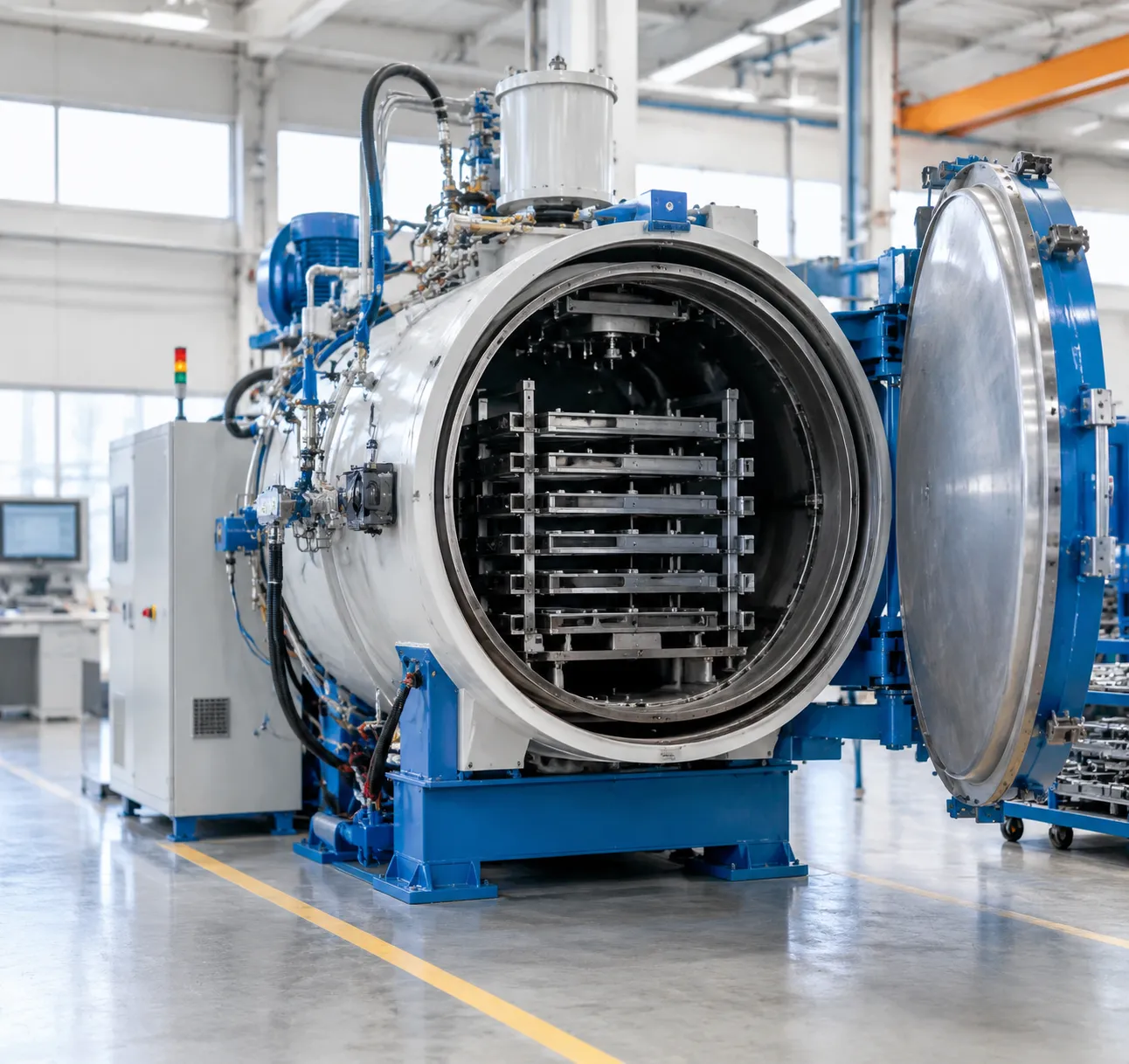
Choosing between a low-pressure carburizing vacuum furnace and traditional gas carburizing comes down to surface quality, part distortion limits, and long-term operating costs. We engineer our vacuum systems to eliminate the common metallurgical drawbacks and post-processing steps associated with legacy atmosphere methods.
| Process Feature | Low-Pressure Carburizing (LPC) | Conventional Gas Carburizing |
|---|---|---|
| Process Atmosphere | Sub-atmospheric hydrocarbon vacuum (e.g., Acetylene at 2–10 mbar) | Endothermic carrier gas mixture ($CO/CO_2/H_2/N_2$) at atmospheric pressure |
| Intergranular Oxidation (IGO) | Zero IGO; bright, metallic surface finish | Typical IGO depth of 10–25 µm requiring post-machining |
| Surface Cleanliness | Clean and soot-free; no degreasing needed | Oxidation scale, soot residue, and quench oil residue |
| Quenching Method | Integrated high-pressure gas quenching ($N_2$ or $He$ up to 20 bar) | Liquid quench oil requiring secondary washing and tempering lines |
| Part Distortion | Low, repeatable distortion via uniform gas flow regulation | Higher distortion caused by liquid oil boiling phases and thermal gradients |
| Cycle Flexibility | Boost-diffuse cycle up to 1050°C for rapid case depth development | Limited to lower operating ranges (880–930°C) to protect refractory linings |
Atmosphere Control and Surface Integrity
While a traditional controlled atmosphere furnace relies on continuous endothermic gas generation and oxygen probes to maintain carbon potential, our LPC vacuum process introduces hydrocarbon pulses directly into the heated workload chamber. Operating under vacuum completely avoids oxygen exposure, preventing intergranular oxidation (IGO), surface decarburization, and soot buildup. This delivers uniform case depth across narrow gear roots, blind holes, and complex splines.
Quenching Flexibility and Clean Handling
Pairing low-pressure carburizing with a quick quench vacuum furnace with gas quenching simplifies the entire heat-treatment workflow:
No post-wash washing lines: Workpieces exit the chamber clean, dry, and ready for tempering or final assembly without chemical degreasing.
Tunable cooling dynamics: Programmable gas pressure and multi-directional flow control minimize thermal shock, keeping dimensional distortion within tight machining tolerances.
Safer work environment: Eliminates open flames, flammable gas exhausts, oil mist, and toxic effluent disposal.
Operating Economics and Long-Term Return
While a vacuum carburizing system involves a higher initial capital outlay than a basic atmosphere box furnace, it generates substantial operational savings:
Shorter cycle times: Higher permissible carburizing temperatures (up to 1050°C) cut process cycle duration by 30% to 50%.
Zero idle consumption: Vacuum furnaces use zero process gas when idling between production runs.
Lower finishing costs: Eliminating IGO and reducing core distortion allows for smaller post-heat-treatment grinding allowances, lowering tooling wear and scrap rates.
Furnace Configurations and Automation Options
We design our low-pressure carburizing vacuum furnace systems with modular architectures to match specific factory footprints, batch sizes, and production throughput targets.
Single-Chamber vs. Multi-Chamber Vacuum Carburizing Systems
Selecting the right layout depends on your target volume, part variety, and cycle timing requirements:
-
- Single-Chamber LPC Furnaces: Ideal for job shops, commercial heat treaters, and medium-volume manufacturers requiring flexible batch processing. Heating, low-pressure carburizing, and high-pressure gas quenching occur inside a single vessel, minimizing floor space requirements and capital cost.
- Multi-Chamber Vacuum Systems: Engineered for high-throughput, continuous serial manufacturing. Workloads move through separate heating, carburizing, and gas-quench chambers via automated internal transfer mechanisms. This isolates thermal zones, shortens cycle times, and keeps the carburizing chambers continuously hot for maximum energy efficiency.
To evaluate which architecture matches your plant capacity, review our detailed guide comparing single vs double vs triple chamber vacuum furnaces for industrial heat treatment.
| Configuration Type | Primary Application | Throughput Capacity | Quench Integration | Footprint & Flexibility |
|---|---|---|---|---|
| Single-Chamber LPC | Small-to-medium batches, diverse part geometries, R&D | Flexible batch cycles (1–3 loads/shift) | Integrated cold-wall gas quench (up to 20 bar) | Compact footprint, rapid recipe changeovers |
| Two-Chamber LPC | Dedicated gear lines, medium-high production | High (continuous sequence) | Separate high-speed gas quench chamber | Moderate footprint, isolated carburizing zone |
| Multi-Chamber Modular Line | High-volume automotive, standard gear components | Continuous 24/7 serial throughput | Multi-directional high-pressure gas quenching | Modular cell layout, fully automated load distribution |
Integrated Production Lines and Factory MES Integration
We integrate our vacuum carburizing system solutions directly into broader automated manufacturing cells to eliminate manual intervention between operations:
-
- Pre- and Post-Treatment Integration: Seamless line layouts incorporating pre-wash stations, vacuum de-oiling units, pre-heating chambers, and continuous tempering furnaces.
- Automated Load Transfer: Rail-guided vehicles (RGVs), overhead gantry loaders, and robotic loading cells that transfer charged baskets automatically between wash, carburize, quench, and temper stations.
- Factory MES and SCADA Connectivity: Standard industrial communication interfaces (OPC UA, Profinet, Modbus) for complete process data logging, batch traceability, CQI-9 compliance recording, and real-time recipe execution.
Custom Fixture, Basket, and Tray Engineering
Carburizing gas penetration and uniform cooling depend heavily on part positioning. We engineer custom alloy fixtures, lightweight carbon-composite (CFC) grids, and stacking baskets designed specifically for your components:
-
- High-Flow CFC Fixturing: Low thermal mass reduces cycle heating energy and prevents quenching heat sink shadows, ensuring uniform gas flow across blind holes, splines, and gear teeth.
- Distortion-Mitigating Nesting: Custom part holders keep long shafts vertical and thin-walled ring gears securely supported during 20-bar gas quenching cycles to minimize runout and post-grind allowances.
Site Preparation, Utilities, and Installation Requirements
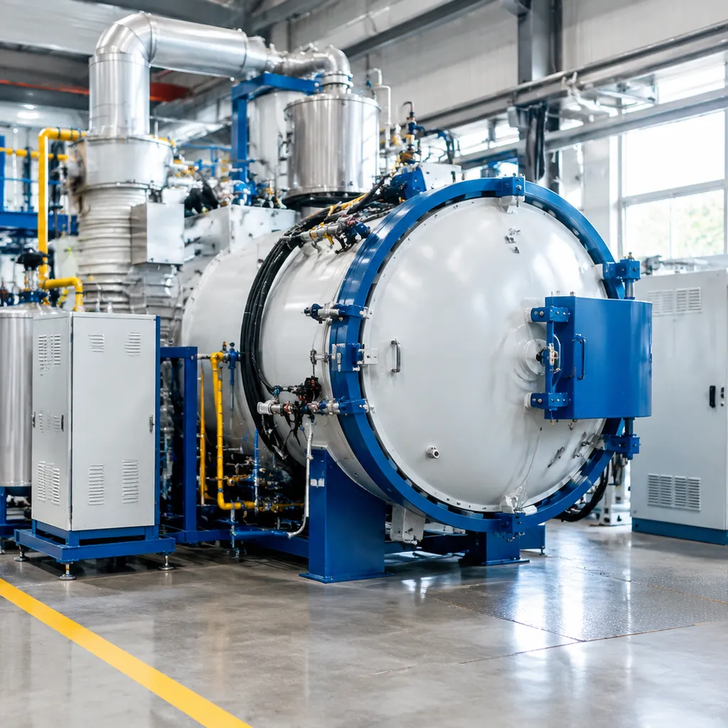
Proper site preparation ensures smooth commissioning, safe operation, and peak uptime for your low-pressure carburizing vacuum furnace. We collaborate directly with your plant engineering team to verify structural, electrical, and utility readiness before delivery.
Workshop Footprint, Clearances, and Foundation
A standard vacuum carburizing system requires adequate floor area for the main furnace vessel, the vacuum pumping skid, gas quenching manifolds, power cabinets, and material handling zones.
-
- Foundation Requirements: Standard reinforced concrete floor (minimum 200–300 mm thickness, capable of supporting 5–15 metric tons depending on furnace model and charge weight). No isolated deep pits are required for standard horizontal units.
- Clearance Zones: Maintain a minimum clearance of 1.5 to 2.0 meters around the perimeter for vacuum pump maintenance, element replacement, and electrical cabinet access.
- Overhead Clearance: Ensure sufficient crane or forklift clearance above the quench motor housings and vessel doors for loading and periodic maintenance.
Power, Cooling Water, and Pneumatic Utility Demands
Consistent utility delivery prevents process interruptions and protects graphite hot zones and diffusion pumps.
| Utility Parameter | Requirement / Specification | Purpose |
|---|---|---|
| Main Power Supply | 380V / 400V / 480V (±10%), 3-Phase, 50/60 Hz | Heating elements, blowers, and vacuum pump motors |
| Control Power | 24V DC / 220V AC dedicated clean supply | PLC, touchscreen HMI, and digital instrumentation |
| Cooling Water (Closed Loop) | Industrial treated water, 20–30°C, 3–5 bar, pH 7.0–8.5 | Shell cooling, vacuum pump jackets, and heat exchangers |
| Emergency Cooling Water | Dedicated gravity tank or backup water loop | Thermal protection during sudden main power outages |
| Pneumatic Supply | Dry, filtered instrument air: 6.0–8.0 bar (dew point ≤ -40°C) | Vacuum valve actuation, door locks, and gas dampers |
Process Gas Storage, Piping, and Safety Ventilation
Operating an LPC vacuum furnace involves hydrocarbon process gases alongside high-pressure inert gases. Planning these storage and line distribution systems early avoids installation delays.
-
- Carburizing Gas Supply: High-purity acetylene (C_2H_2 ge 99.8%) or propane line distribution routed through 316L stainless steel tubing with orbital welds to eliminate contamination and leaks.
- Purging and Quench Gas: Industrial nitrogen (N_2 ge 99.999%) supply tanks or bulk liquid storage capable of feeding high-flow injection manifolds for sub-atmospheric purging and high-pressure gas quenching cycles.
- Safety Monitoring: Install ambient gas leak detectors and emergency shutoff valves linked directly to the furnace safety PLC.
- Exhaust Lines: Pumping system exhaust lines must vent directly outside the facility following local environmental codes, especially when analyzing how a vacuum furnace operates under hydrocarbon pulsing cycles.
Pre-Installation Engineering Support and Utility Audits
To streamline deployment, we provide comprehensive pre-installation support well in advance of equipment arrival:
-
- Custom Layout Drawings: Detailed 2D/3D CAD layouts showing machine footprints, utility drop locations, maintenance zones, and loader travel paths.
- Civil & Utility Interface Sheets: Explicit pipe sizes, electrical conduit entry points, and connection flanges.
- Pre-Delivery Utility Audits: Remote engineering verification of plant water flow, electrical supply stability, and gas line pressures.
- Commissioning Readiness: Coordination handled through our after-sales technical support team to supervise rigging, final hookups, cold commissioning, and process recipe validation on site.
Operation, Preventive Maintenance, and Safety Standards for LPC Vacuum Furnaces
Reliable day-to-day operation of a low-pressure carburizing vacuum furnace requires disciplined process controls, scheduled mechanical checks, and redundant safety systems. We build our equipment with automated workflows and robust hardware to ensure continuous uptime, strict metallurgical compliance, and a safe production environment.
Standard Operating Procedures and Recipe Management
Our PLC control interface simplifies daily workflow while maintaining tight control over heat-treatment cycles:
-
- Recipe Automation: Operators select pre-programmed recipes that manage thermal ramp rates, hydrocarbon pulse sequences, diffusion intervals, and quench gas pressures without manual intervention.
- Access Control: Multi-tier user levels (Operator, Maintenance, Metallurgist) prevent unauthorized recipe edits or manual overrides during active cycles.
- Data Traceability: Every process parameter—including vacuum level, zone temperatures, gas pulse duration, and quenching speed—is logged in real time for audit compliance (CQI-9 and AMS 2750).
- Operator Training: We provide comprehensive training programs covering charge loading, program setup, door seal inspection, and standard recovery procedures.
Routine Maintenance Schedule
Preventive maintenance keeps your vacuum carburizing furnace running at peak efficiency and avoids unexpected downtime. Understanding optimal heat transfer in a vacuum furnace relies directly on keeping heating zones and thermal insulation clean and free of carbon buildup.
| Component | Frequency | Action / Inspection Task |
|---|---|---|
| Door Seals & O-Rings | Daily / Weekly | Clean sealing surfaces, check for cracks, and lightly apply vacuum-rated grease. |
| Rotary & Booster Pumps | Monthly | Inspect oil levels and color; change oil and exhaust filters per operating hours. |
| Heating Elements | Monthly | Inspect graphite or metallic elements, support clips, and connections for degradation. |
| Gas Injection Nozzles | Quarterly | Inspect injector tips for carbon accumulation; clean or clear gas supply lines. |
| Quench Gas Blower & Valves | Bi-Annually | Check motor bearings, test high-speed valve actuation, and verify gas cooling circuit. |
| Chamber Insulation Hot Zone | Annually | Inspect graphite felt or CFC shielding for thermal erosion or mechanical wear. |
Instrumentation Calibration and Leak Rate Verification
Consistent case hardening depends on accurate temperature measurement and maintaining a leak-tight vacuum vessel:
-
- Thermocouple Verification: Scheduled System Accuracy Tests (SAT) and Temperature Uniformity Surveys (TUS) ensure multi-zone heating consistency across all operational ranges.
- Automated Leak Rate Testing: The system runs automated pump-down and rate-of-rise tests before carburizing to confirm chamber integrity and eliminate atmospheric contamination.
- Pressure Sensor Calibration: Capacitance manometers and Pirani gauges undergo routine calibration to ensure precise sub-atmospheric pressure control during hydrocarbon injection.
Safety Systems and Interlocks
Working with hydrocarbon process gases and high-pressure quenching systems requires failsafe protection. Our LPC vacuum furnace designs integrate multi-layer safety protections:
-
- Over-Temperature Protection: Independent analog and digital safety controllers immediately cut heating power if temperatures exceed preset limits.
- Vacuum and Gas Interlocks: Carburizing gas valves cannot open unless chamber pressure, door locks, and minimum ignition temperatures are confirmed.
- Emergency Gas Purge: In the event of power loss or process interruption, the system automatically isolates the reactive gas line and purges the chamber with high-purity nitrogen.
- Fault Diagnostics: Real-time software monitors pump currents, cooling water flow, pneumatic air pressure, and gas manifold levels, triggering safe shutdown sequences if parameters drift.
Manufacturer Support and Commissioning
We support every vacuum carburizing system through its entire operational lifecycle:
-
- On-Site Installation & Commissioning: Our engineers manage utility hookup verification, thermal profiling, SAT/TUS testing, and first-batch production runs.
- Spare Parts Availability: We maintain dedicated stock of critical components, including heating elements, thermocouples, vacuum seals, and solenoid valves for rapid dispatch.
- Remote Technical Diagnostics: Integrated secure industrial routers allow our engineering team to provide live troubleshooting, recipe optimization, and software diagnostics directly to your plant floor.
Low-Pressure Carburizing Vacuum Furnace FAQs
What is the difference between vacuum carburizing and low-pressure carburizing?
Vacuum carburizing and low-pressure carburizing (LPC) refer to the same fundamental process. Early vacuum carburizing systems operated at higher partial pressures using propane, which often created excessive soot. Modern low-pressure carburizing runs at sub-atmospheric pressures (typically 1 to 10 mbar) using acetylene gas. This low-pressure approach ensures soot-free operation, deep hole penetration, and precise carbon transfer.
How does low-pressure carburizing prevent intergranular oxidation (IGO)?
Conventional gas carburizing uses oxygen-bearing carrier gases (such as CO, CO₂, and H₂O), which react with alloying elements like chromium, manganese, and silicon at the grain boundaries to form surface oxides. An LPC vacuum furnace operates in an oxygen-free vacuum chamber. Because the atmosphere contains only pure hydrocarbon gases and inert purge gases, surface oxidation and IGO are completely eliminated.
Can an LPC vacuum furnace handle high-pressure gas quenching?
Yes. Our vacuum carburizing systems are engineered to integrate high-pressure gas quenching (HPGQ) directly within the same chamber or in a connected quench module.
| Parameter | Gas Quench Specification |
|---|---|
| Cooling Media | High-purity Nitrogen (N₂) or Helium (He) |
| Quench Pressure Range | 2 bar to 20 bar (customizable) |
| Flow Control | Reversible, bi-directional, and variable-speed gas circulation |
| Key Advantage | Clean, dry parts with zero oil residue and reduced distortion |
How is case depth and carbon profile controlled during the cycle?
We control effective case depth (ECD) and surface carbon concentration using alternating boost (hydrocarbon injection) and diffuse (vacuum soaking) steps.
-
- Boost Phase: Acetylene dissociates on the clean metal surface, delivering rapid carbon saturation up to the austenite solubility limit.
- Diffuse Phase: Gas injection stops, and carbon diffuses inward toward the core under vacuum.
- Simulation Integration: Our automated PLC calculates the exact cycle timing and pulse count based on steel grade, temperature, and target case depth.
What hydrocarbon gases are used for the carburizing boost phase?
Acetylene (C₂H₂) is our standard process gas due to its high cracking efficiency and effective penetration into complex root geometries and blind holes with minimized soot formation. Depending on metallurgical requirements, we can also configure the injection manifold for propane (C₃H₈) or ethylene (C₂H₄).
How do we choose between single-chamber and multi-chamber configurations?
Choosing the right layout depends on your production throughput, part variability, and footprint requirements:
-
- Single-Chamber LPC Systems: Ideal for commercial heat treaters and varied batch production requiring flexible cycle recipes in a compact footprint. You can review our selection of specialized vacuum furnaces to evaluate standard batch system footprints.
- Multi-Chamber LPC Lines: Designed for high-volume automotive and transmission production. Dedicated heating, carburizing, and quenching chambers operate simultaneously to maintain high continuous output.
What technical details are needed to receive a custom furnace quote?
To help our team engineer the right system configuration, provide the following details in your inquiry:
-
- Part Specifications: Component drawings, dimensions, geometry, and base steel grades (e.g., 20CrMnTi, 8620, 16MnCr5, 5120).
- Process Targets: Required effective case depth (ECD), surface hardness, core hardness, and distortion tolerances.
- Production Volume: Target gross workload weight per cycle and required throughput (parts or kg per hour).
- Quench Preference: Gas quenching pressure requirements (e.g., 10 bar, 16 bar, 20 bar) or oil quench integration.
- Facility Utilities: Available plant voltage, cooling water capacity, and workshop floor dimensions.