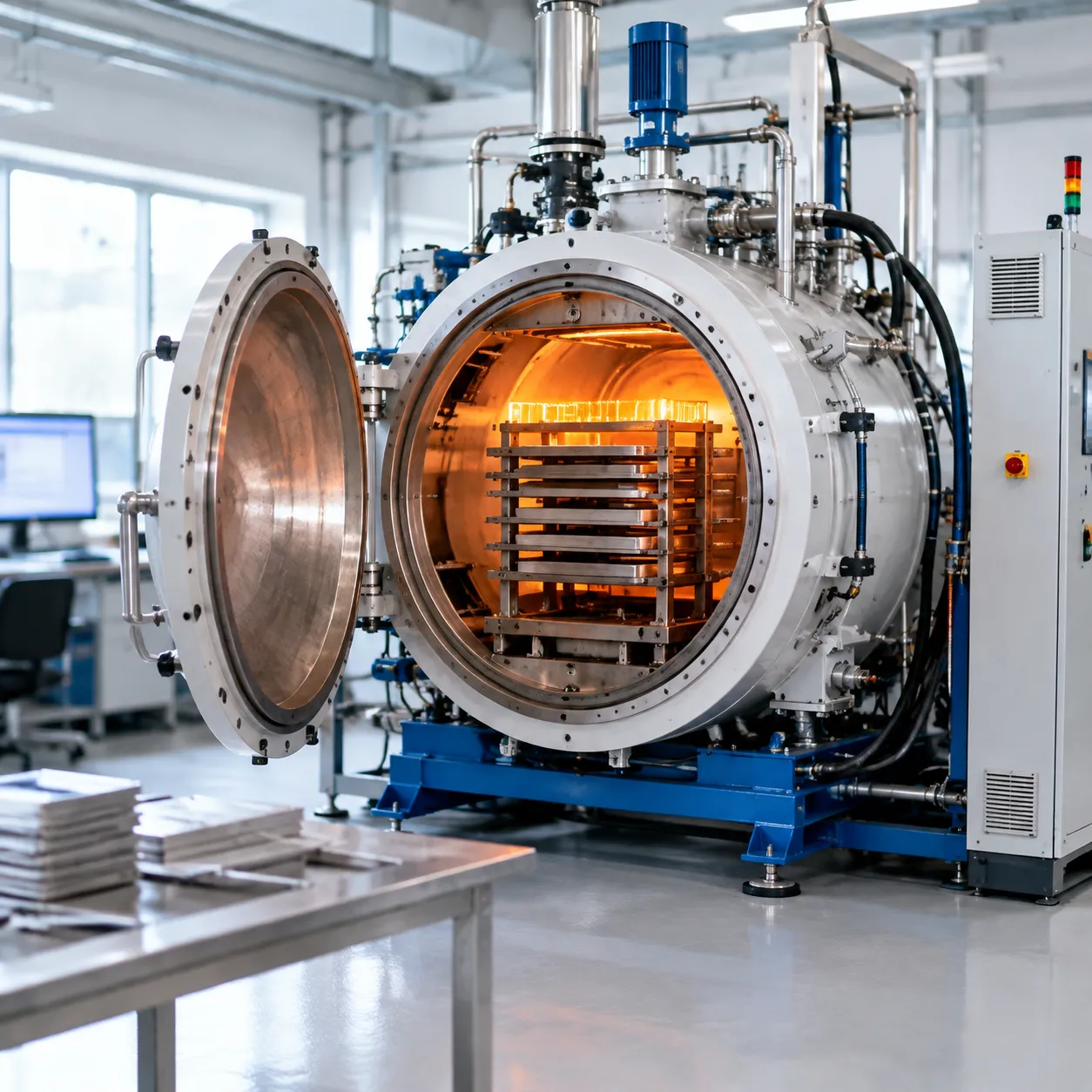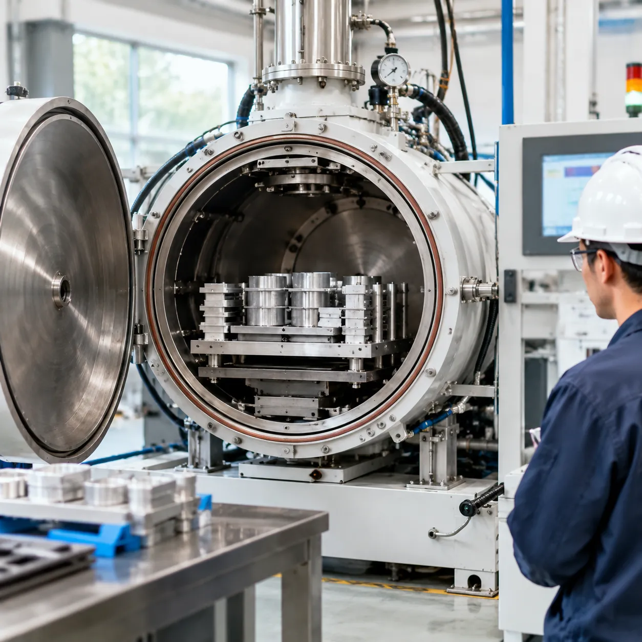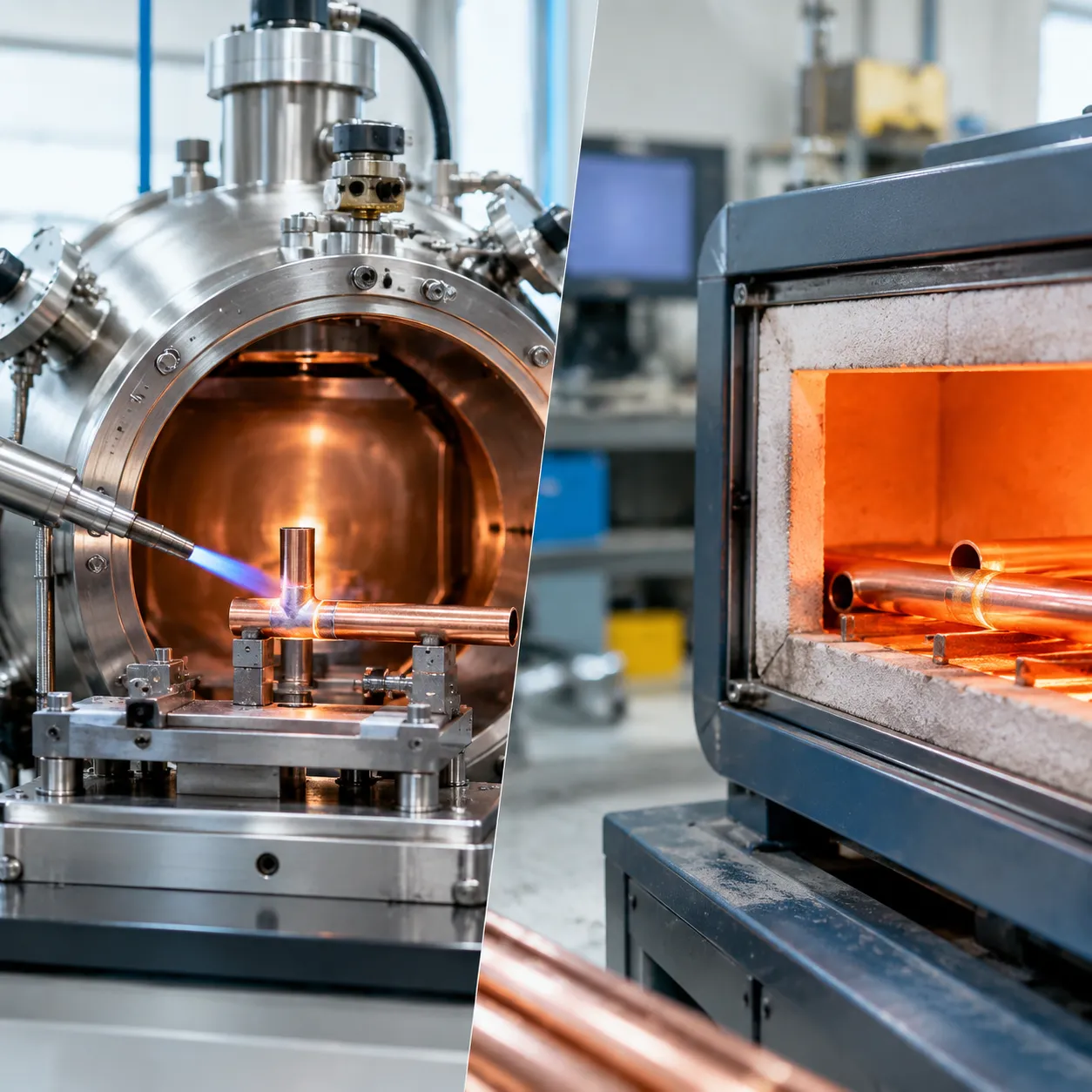
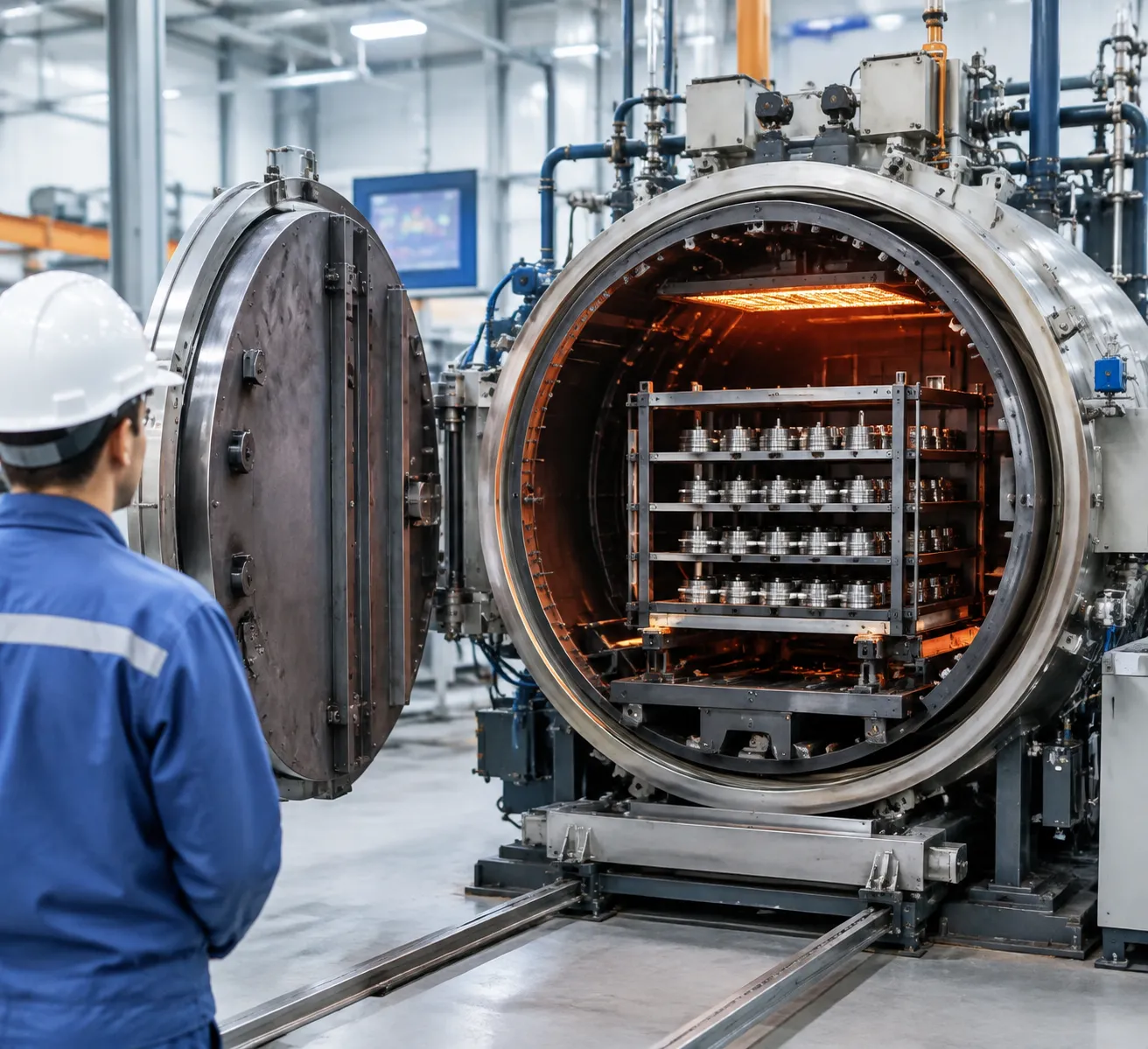
What Is a Vacuum Furnace Brazing Cycle?
A vacuum furnace brazing cycle is a precise thermal joining process where we bond metallic components using a filler alloy with a melting point above 450°C (840°F), but below the liquidus temperature of the base metals. Performed entirely inside an evacuated thermal chamber, the cycle uses controlled heating to trigger capillary action, drawing molten filler metal into narrow gaps between closely fitted parts.
By engineering the heat, vacuum level, and material interactions in an oxygen-free environment, we create high-strength, leak-tight joints without altering the fundamental metallurgy of your base parts.
Core Elements of the Vacuum Brazing Mechanism
-
- Controlled Heat: Elevates the entire assembly uniformly to activate filler metal flow while avoiding thermal shock.
- High-Vacuum State: Removes ambient oxygen, water vapor, and residual gases from the hot zone.
- Filler Metal: Specialized alloys—such as nickel, copper, silver, or gold-based materials—chosen specifically for your base metals.
- Capillary Action: The physical force that draws liquid filler metal deep into joint clearances between 0.012 mm and 0.1 mm.
Why Vacuum Protection Is Essential
Oxidation destroys braze quality. At elevated temperatures, atmospheric oxygen forms oxide films on metal surfaces that block liquid alloy flow and cause joint failure.
-
- Oxidation Prevention: Eliminates atmospheric oxygen so metal surfaces remain clean throughout heating.
- Superior Surface Wetting: Allows liquid filler alloys to spread effortlessly across complex, tight-tolerance geometries.
- Unmatched Joint Integrity: Prevents trapped gas pockets, slag, or porosity, yielding vacuum-tight, high-shear joints.
Vacuum Brazing vs. Traditional Flux-Based Brazing
| Feature | Vacuum Furnace Brazing | Traditional Flux-Based Brazing |
|---|---|---|
| Oxidation Removal | Atmospheric evacuation under high vacuum | Corrosive chemical flux agents |
| Post-Process Cleaning | Zero (Parts exit bright, clean, and dry) | Extensive acid washing and mechanical scrubbing |
| Corrosion Risk | Non-existent | High risk from trapped chemical flux residues |
| Joint Purity | Flawless, void-free, aerospace-grade | Vulnerable to flux inclusions and joint porosity |
| Material Compatibility | Stainless steel, superalloys, titanium, ceramics | Basic copper, brass, and mild steel alloys |
Eliminating chemical flux from the joining process makes our vacuum furnace brazing cycles cleaner, safer, and structurally superior for critical engineering applications.
Main Stages of a Vacuum Furnace Brazing Cycle
1. Pre-cleaning and Component Preparation
-
- Surface Degreasing: Parts undergo ultrasonic cleaning or vapor degreasing to strip oils, lubricants, and fingerprints.
- Oxide Removal: Mechanical abrading or acid pickling removes surface oxides, ensuring clean metal-to-metal contact for uniform wetting.
2. Assembly, Fixturing, and Filler Metal Placement
-
- Joint Clearance: We maintain tight joint gaps (typically 0.012 mm to 0.05 mm) to maximize capillary action.
- Filler Application: Preforms, pastes, or foils are placed directly at the joint interface. For demanding high-temperature components, following a dedicated nickel brazing in vacuum furnace guide ensures correct alloy positioning and flow performance.
- Fixturing: Low-mass fixtures with matching thermal expansion coefficients hold parts in alignment without creating thermal sinks.
3. Chamber Loading and Furnace Setup
-
- Uniform Load Spacing: Components are arranged to ensure equal radiant heat transfer across the entire workload.
- Thermocouple Attachment: Load thermocouples are placed on both thin and thick sections of the parts to monitor real-time temperature uniformity.
4. Pump-Down and Vacuum Evacuation
-
- Primary Evacuation: Roughing pumps strip out bulk atmosphere and moisture from the hot zone.
- High Vacuum Stage: Diffusion or turbomolecular pumps drop vacuum pressure to eliminate trace oxygen and residual gases, preventing metal oxidation before heating starts.
5. Preheating and Thermal Equalization
-
- Ramp-Up Rates: Gradual heating ramps minimize thermal shock on complex assemblies.
- Outgassing Holds: Intermediate temperature holds equalize thermal mass between thick and thin parts while burning off residual binder materials safely.
6. Brazing Soak Above Liquidus Temperature
-
- Rapid Ramp to Peak: The furnace ramps quickly to the brazing soak temperature, exceeding the filler alloy's liquidus point.
- Capillary Action: Molten filler metal flows completely into the joint gap.
- Precise Soak Time: Holding the peak temperature just long enough ensures complete joint penetration while avoiding base metal erosion or over-diffusion.
7. Cooling and Gas Quenching
-
- Vacuum Solidification: The load cools under vacuum until the filler metal fully solidifies below its solidus point.
- Forced Gas Quenching: High-purity argon or nitrogen gas is injected under pressure (typically 2 to 10 bar) for fast forced cooling. Reviewing real-world vacuum furnace applications and benefits highlights how high-speed gas quenching retains desirable base metal grain structure and shortens overall production cycles.
8. Unloading and Post-Cycle Inspection
-
- Visual Checks: Parts are unloaded free of oxidation or discoloration, featuring continuous braze fillets.
- Joint NDT Verification: High-integrity assemblies undergo helium leak testing, dimensional inspection, or ultrasonic testing to confirm full joint fill.
Key Parameters That Control Brazing Quality
| Parameter | Target Range | Impact on Joint Quality |
|---|---|---|
| Vacuum Level | 10⁻³ to 10⁻⁵ mbar | Eliminates oxides, promotes outgassing, and maximizes alloy wetting. |
| Brazing Soak Temperature | 25°C to 50°C above liquidus | Ensures complete melting and smooth brazing filler metal flow. |
| Brazing Soak Time | 5 to 20 minutes | Guarantees complete capillary action without base metal erosion. |
| Brazing Joint Clearance | 0.025 mm to 0.10 mm | Generates optimal capillary pressure to draw filler metal into the joint gap. |
| Quench Gas Pressure | 2 to 10 bar (Inert Gas) | Rapidly solidifies alloy while preventing distortion during gas quenching in vacuum furnace operations. |
Vacuum Level and Outgassing
A proper vacuum level for brazing prevents surface oxidation without using chemical fluxes. Maintaining high vacuum conditions removes trapped air, residual oils, and volatiles during heating:
Oxide Breakdown: High vacuum breaks down surface oxides, enabling molten filler metal to wet base alloys directly.
Outgassing Control: Thermal holds allow outgassing of volatile contaminants before reaching peak brazing heat.
Precise Vacuum Furnace Temperature Control
Executing a reliable vacuum furnace brazing cycle demands precise high-temperature vacuum processing equipment to prevent part distortion. Advanced vacuum furnace temperature control maintains uniform thermal profiles across complex geometries:
Ramp Rates: Controlled heating rates minimize thermal stress between thin and thick part sections.
Thermal Equalization: Strategic preheat holds equalize temperature across the entire load.
Multi-Zone Heating: Independent zone heating maintains temperature uniformity within ± 5 °C throughout the hot zone.
Soak Time and Joint Clearance Dynamics
Balancing the brazing soak temperature and duration dictates final bond strength:
Under-soaking Risks: Insufficient time causes cold joints, un-melted filler alloy, and incomplete joint fill.
Over-soaking Risks: Excessive soaking leads to base metal erosion, unwanted intermetallic compounds, and grain growth.
Clearance Precision: Tight joint gaps maximize capillary force, pulling filler metal deep into long seams.
Controlled Gas Quenching and Cooling Management
Once the filler metal solidifies below its solidus temperature, we initiate high-purity inert gas cooling (argon or nitrogen). Regulating the cooling rate prevents part distortion, controls metallurgy, and ensures bright, clean finished assemblies.
Vacuum Furnace Components That Influence the Brazing Cycle
The success of a vacuum furnace brazing cycle relies heavily on the physical architecture of the equipment. When we engineer high-performance systems, we focus on key hardware components that directly control thermal uniformity, atmospheric purity, and process repeatability.
Hot Zone Design and Thermal Transfer Efficiency
Hot zone geometry dictates how uniformly radiant heat reaches the load. Optimized circular or rectangular hot zones prevent cold spots, ensuring equal thermal absorption across complex workpieces so the filler metal melts evenly across every joint.
Heating Elements and Insulation Performance
-
- Graphite vs. Metallic Elements: Graphite elements provide high durability and rapid heating, while metallic elements (molybdenum or tungsten) ensure an ultra-clean environment for sensitive alloys.
- Insulation Packages: Multi-layer metallic radiation shields or high-purity graphite felt retain heat efficiently, enabling accurate vacuum furnace temperature control throughout the soak phase.
Vacuum Pumping Systems
The pumping package transitions the chamber through distinct vacuum stages:
1. Roughing Stage: Mechanical pumps rapidly evacuate atmospheric air, moisture, and initial surface contaminants.
2. High-Vacuum Stage: Diffusion or turbomolecular pumps lower the chamber to target vacuum pressure levels, rapidly removing outgassing products to stop oxidation before filler metal flow begins.
Automated Control Systems and Data Logging
Programmable logic controllers (PLCs) automate multi-segment heat profiles. Real-time curve logging continuously tracks temperature ramps, hold times, and chamber pressure, creating full digital traceability for quality assurance.
High-Speed Gas Quenching System Operation
Controlled cooling solidifies the braze alloy cleanly and reduces overall process time. Utilizing a single-chamber vacuum furnace with high-pressure gas quenching allows precise inert gas distribution (nitrogen or argon), preventing thermal shock and part distortion. For heavy production loads, a dedicated quick quench vacuum furnace delivers rapid forced cooling while preserving high joint integrity.
Common Materials Processed in a Vacuum Furnace Brazing Cycle
Stainless Steel Brazing Dynamics
Stainless steels naturally form a tough chromium oxide layer that prevents braze alloy wetting. High vacuum heat treatment at elevated temperatures breaks down these surface oxides without flux.
Best Filler Metals: Nickel-based (BNi series) and copper filler alloys.
Key Focus: Managing outgassing in vacuum brazing to keep base metal surfaces pure and bright.
Nickel-Based Superalloys
Superalloys like Inconel and Hastelloy power high-temperature aerospace and energy components. To achieve leak-tight, high-strength joints across complex nickel assemblies, we utilize specialized equipment like our high-performance vacuum brazing furnace.
Oxide Control: Superalloys containing aluminum or titanium form stable oxides that require lower base pressures to clear.
Joint Integrity: Delivers high creep strength and oxidation resistance at service temperatures above 800°C.
Titanium and Reactive Metals
Titanium, zirconium, and tantalum act as gas getters, rapidly absorbing oxygen, nitrogen, and hydrogen at high temperatures.
| Process Factor | Requirement for Titanium Brazing |
|---|---|
| Vacuum Pressure | Strict high vacuum (10^-4 Torr or deeper) |
| Quench Gas | Ultra-pure Argon (Nitrogen causes surface nitriding) |
| Main Risk | Intermetallic brittleness from atmospheric contamination |
Copper and Copper Alloys
Copper offers superior thermal conductivity and outstanding brazing filler metal flow.
Wetting & Capillary Action: Molten silver or BCuP alloys flow smoothly across clean copper surfaces.
Thermal Management: Precise temperature ramp rates prevent grain growth and thin-wall joint erosion.
Ceramics and Metal-Ceramic Precision Joining
Directly joining ceramics (Alumina, Zirconia, Silicon Nitride) to metals requires active alloy brazing.
Active Fillers: Alloys containing titanium react chemically with ceramic surfaces, enabling direct wetting without prior metallization.
Thermal Mismatch: Controlled heating and slow cooling profiles eliminate joint cracking caused by mismatched thermal expansion coefficients.
Typical Vacuum Furnace Brazing Cycle Parameters
Establishing the correct vacuum furnace brazing cycle parameters is critical to achieving clean, high-strength joints without damaging your base metals. A standard thermal profile balances heating rates, vacuum levels, and soak durations to ensure complete outgassing and optimal capillary flow.
Example Vacuum Brazing Cycle Breakdown
| Segment | Temperature Range | Vacuum / Pressure Level | Hold Time | Primary Objective |
|---|---|---|---|---|
| Initial Evacuation | Ambient | 10⁻³–10⁻⁵ mbar | Until setpoint reached | Remove atmospheric air and moisture |
| Outgas Soak | 500°C – 600°C | High Vacuum | 15 – 30 mins | Equalize core temp; burn off residue |
| Thermal Stabilization | 50°C below Solidus | High Vacuum | 10 – 20 mins | Minimize thermal distortion across part mass |
| Brazing Soak (Peak) | 25°C – 50°C above Liquidus | High Vacuum | 5 – 15 mins | Flow filler alloy into joint clearances |
| Controlled Solidification | Liquidus to Solidus | High Vacuum / Partial Pressure | 5 – 10 mins | Freeze braze metal before quenching |
| Gas Quenching | Solidus to <100°C | 2 – 10 bar Argon/Nitrogen | Rapid forced cooling | Cool parts safely and shorten cycle time |
Key Factors Altering Brazing Cycle Recipes
No single thermal recipe fits every assembly. We alter brazing cycle parameters based on three primary variables:
-
- Base Metal Sensitivity: Reactive metals like titanium demand deeper vacuum levels, while stainless steels require controlled heating rates to prevent sensitization.
- Filler Alloy Selection: High-temperature nickel or copper filler alloys require a higher brazing soak temperature than lower-melting silver or aluminum braze alloys.
- Load Mass and Density: Dense furnace loads need longer equalization holds during preheat stages to eliminate thermal deltas between outer parts and core fixtures.
Why Customization and Process Validation Are Essential
Using off-the-shelf heating profiles often leads to joint voids, excessive filler runoff, or incomplete wetting. Customizing your thermal profile guarantees that outgassing completes before the filler alloy melts, preserving joint integrity.
Validating each custom recipe through pyrometry and routine vacuum furnace calibration prevents unexpected batch failures. Aligning these tailored parameters with your standard vacuum furnace heat treatment process ensures repeatable, leak-tight results across every production run.
Common Problems in Vacuum Brazing and How to Prevent Them
Even minor variations in part preparation or atmosphere control can disrupt a vacuum furnace brazing cycle. We regularly help engineering teams isolate and eliminate these common process failures to protect part yield and maintain leak-tight joint integrity.
Preventing Oxidation, Discoloration, and Residual Contamination
Post-braze oxidation or surface discoloration usually points to vacuum leaks, contaminated cooling gas, or residual oils left on components.
-
- Thorough Pre-Cleaning: Remove all machining oils, lubricants, and oxides using ultrasonic aqueous cleaning or solvent degreasing prior to loading.
- Outgassing Control: Ensure components and fixtures are thoroughly dry to prevent outgassing in vacuum brazing from degrading high-vacuum pressure levels.
- Gas Purity: Use high-purity argon or nitrogen (99.999% purity or higher) during gas quenching cycles to prevent hot metal surfaces from oxidizing.
- Leak Rate Audits: Perform routine rate-of-rise tests on your chamber to detect micro-leaks in shaft seals, valves, or O-rings.
Solving Poor Filler Metal Flow and Wetting Issues
When filler alloys fail to spread smoothly across the joint surface, capillary action breaks down completely.
| Root Cause | Process Impact | Recommended Corrective Action |
|---|---|---|
| Surface Oxides | Prevents wetting; alloy balls up | Improve pre-cleaning; ensure vacuum level is deep enough before melting |
| Incorrect Temperature | Alloy freezes prematurely | Recalibrate furnace sensors; hold load at proper brazing soak temperature |
| Improper Joint Gap | Alloy cannot flow into joint | Adjust machining tolerances for optimal joint clearance (0.025 mm to 0.10 mm) |
Eliminating Voids, Leaks, and Weak Braze Joints
Porosity and unfilled cavities weaken joint mechanical strength and cause pressure test failures in critical assemblies.
-
- Optimize Thermal Equalization: Allow sufficient hold time during preheat stages so core and surface temperatures equalize before reaching alloy liquidus.
- Precise Alloy Dosing: Calculate filler metal volume accurately to ensure complete joint fill without leaving starved zones.
- Venting Trapped Gases: Design blind holes and deep recesses with vent channels so expanding gas escapes during initial vacuum pump-down.
Controlling Part Distortion Through Fixturing and Cooling Adjustments
High thermal gradients during rapid heating or aggressive gas quenching cause delicate assemblies to warp or twist.
-
- Low-Mass Fixturing: Use molybdenum or graphite fixtures designed to match the thermal expansion coefficients of your base metals.
- Controlled Heating Rates: Slow down heating ramp rates through critical phase-transformation zones to equalize load temperature.
- Balanced Gas Quenching: Adjust quench gas pressure and direction to optimize heat transfer in a vacuum furnace without inducing thermal shock on thin-walled sections.
Avoiding Excessive Filler Runoff and Overheating
Overheating or holding a load at peak temperature too long causes filler metal to migrate away from the joint, erode base metals, or pool on visible surfaces.
-
- Limit Peak Soak Time: Restrict time above liquidus to the minimal duration required for complete capillary flow (typically 5 to 15 minutes).
- Apply Braze Stop-Off: Apply ceramic stop-off coatings around joint boundaries to contain brazing filler metal flow where precision is required.
- Control Base Metal Dissolution: Lower peak temperatures when using reactive nickel or copper filler alloys on thin-gauge base materials.
Fixing Inconsistent Cycle Results and Vacuum Instability
Unstable vacuum levels and batch-to-batch variations signal mechanical wear or drift in furnace control hardware. Reviewing the basic principles of how a vacuum furnace works helps maintenance teams distinguish between pump degradation and outgassing loads.
-
- Standardize Recipes: Lock down automated, multi-segment recipes to enforce fixed heating rates, vacuum hold levels, and cooling profiles across every shift.
- Maintain Vacuum Pumping Systems: Service mechanical roughing pumps and high-vacuum diffusion or turbomolecular pumps regularly to ensure steady pump-down speeds.
- Calibrate Thermal Sensors: Recalibrate control and load thermocouples routinely to ensure precise multi-zone temperature uniformity across every batch.
How to Optimize a Vacuum Furnace Brazing Cycle
Optimizing your vacuum furnace brazing cycle is the most direct way to eliminate joint defects, reduce total process times, and guarantee repeatable quality across high-volume production runs. We focus on five practical operational adjustments to maximize thermal efficiency and yield.
1. Upgrade Part Cleaning and Assembly Protocols
-
- Eliminate Surface Contaminants: Solvent degrease and ultrasonically clean all components before assembly. Even minimal organic residue causes outgassing and void formation.
- Control Joint Clearance: Maintain tight, consistent gaps (typically 0.025 mm to 0.075 mm) to maximize capillary action and alloy flow.
- Standardize Alloy Application: Apply brazing pastes or preforms uniformly to prevent joint starvation or excessive filler runoff.
2. Implement Segment-Based Temperature Profiling
-
- Multi-Stage Preheating: Incorporate controlled preheat holds below the solidus temperature to equalize heat across heavy and light sections.
- Mitigate Thermal Shock: Use tailored ramp rates to protect complex geometries from distortion during rapid heating phases.
- Precision Soak Control: Limit time above the liquidus temperature to the exact window needed for complete wetting, preventing base metal erosion.
3. Match Thermal Cycles to Specific Alloys
-
- Optimize Outgassing Dwells: Extend vacuum hold stages when processing binders or volatile coatings to maintain target vacuum pressure levels.
- Tailor Peak Parameters: Adjust peak temperatures and vacuum levels specifically for stainless steel, nickel alloys, or reactive metals.
- Equipment Alignment: Running custom thermal profiles on a modern vacuum heat treatment furnace ensures precise temperature uniformity throughout the hot zone.
4. Optimize Furnace Loading and Thermal Airflow
-
- Use Low-Mass Fixturing: Utilize high-temperature molybdenum or carbon-composite fixtures that minimize thermal mass and absorb less heating energy.
- Space Workpieces Evenly: Arrange loads to allow unobstructed radiant heating during ramp-up and uniform forced gas circulation during cooling.
- Controlled Gas Quenching: Adjust argon or nitrogen cooling pressure to safely accelerate cycle completion without causing quench distortion.
5. Track Process Data for Batch Repeatability
-
- Log Real-Time Thermal Curves: Capture data from both load and control thermocouples to verify actual part temperatures against setpoints.
- Monitor Pressure Spikes: Track vacuum level history during heating to detect micro-leaks or sudden material outgassing immediately.
- Audit Historical Records: Leverage digital batch logs to refine future recipes and maintain full traceable quality control.
Choosing the Right Vacuum Furnace for Brazing
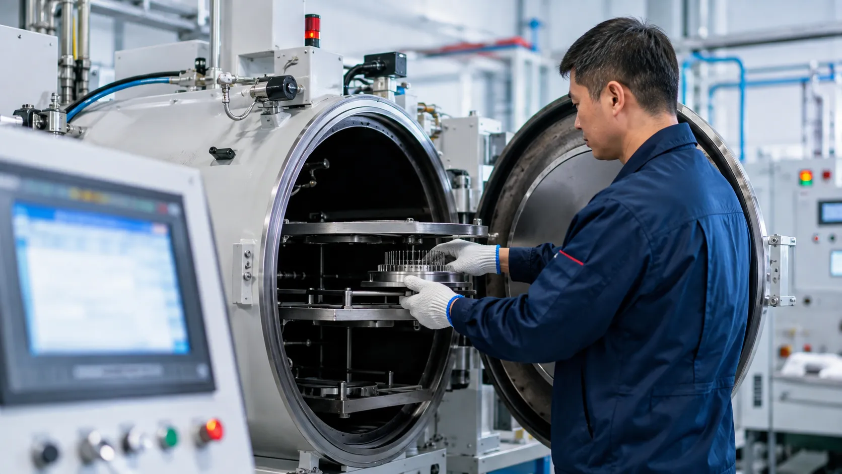
Selecting the right equipment directly dictates the success of your vacuum furnace brazing cycle. Matching furnace capabilities to your production volume, alloy requirements, and joint specs ensures clean, repeatable runs without thermal distortion or unbonded joints. When evaluating advanced vacuum furnaces for high-precision manufacturing, performance metrics must align with your exact metallurgical goals.
Evaluate Key Performance Metrics
-
- Vacuum Depth & Leak Rate: Ensure the system reaches required vacuum levels quickly to prevent alloy oxidation before heat-up.
- Temperature Uniformity: Look for hot zones offering tight thermal distribution across all work zones during the soak phase.
- Quenching Power: High-pressure gas quenching capability speeds up cycle times and preserves core mechanical properties.
Precise Control Drives Down Reject Rates
Inconsistent thermal profiles cause costly scrap, unbonded seams, and filler metal runoff. Advanced vacuum furnace temperature control maintains tight tolerance during critical ramp and soak segments. Precise multi-zone heating prevents localized cold spots, giving you uniform capillary action and consistent joint integrity across every part in the load.
When Custom Thermal Engineering Is Necessary
Standard off-the-shelf units work well for standard parts, but complex manufacturing demands custom engineering. Tailored thermal solutions are necessary when handling:
-
- Oversized, heavy, or non-uniform part loads requiring custom heating element placement.
- Reactive metals like titanium that demand specialized ultra-clean hot zones.
- High-throughput production lines requiring specialized automation and fast-turnaround cooling.
Critical Questions to Ask Before Buying
Before investing in equipment, review our practical vacuum furnace guide and ask suppliers these essential questions:
-
- What is the baseline leak rate and pump-down speed under full load conditions?
- How does the system handle multi-segment recipe programming and real-time data logging?
- What hot zone insulation materials are used to prevent outgassing and contamination?
- Can the cooling system automatically modulate gas pressure to minimize part distortion?
Evaluating these vacuum brazing furnace parameters upfront guarantees reliable process stability, minimizes downtime, and lowers your total cost of ownership.
Vacuum Furnace Brazing Cycle Applications Across Industries
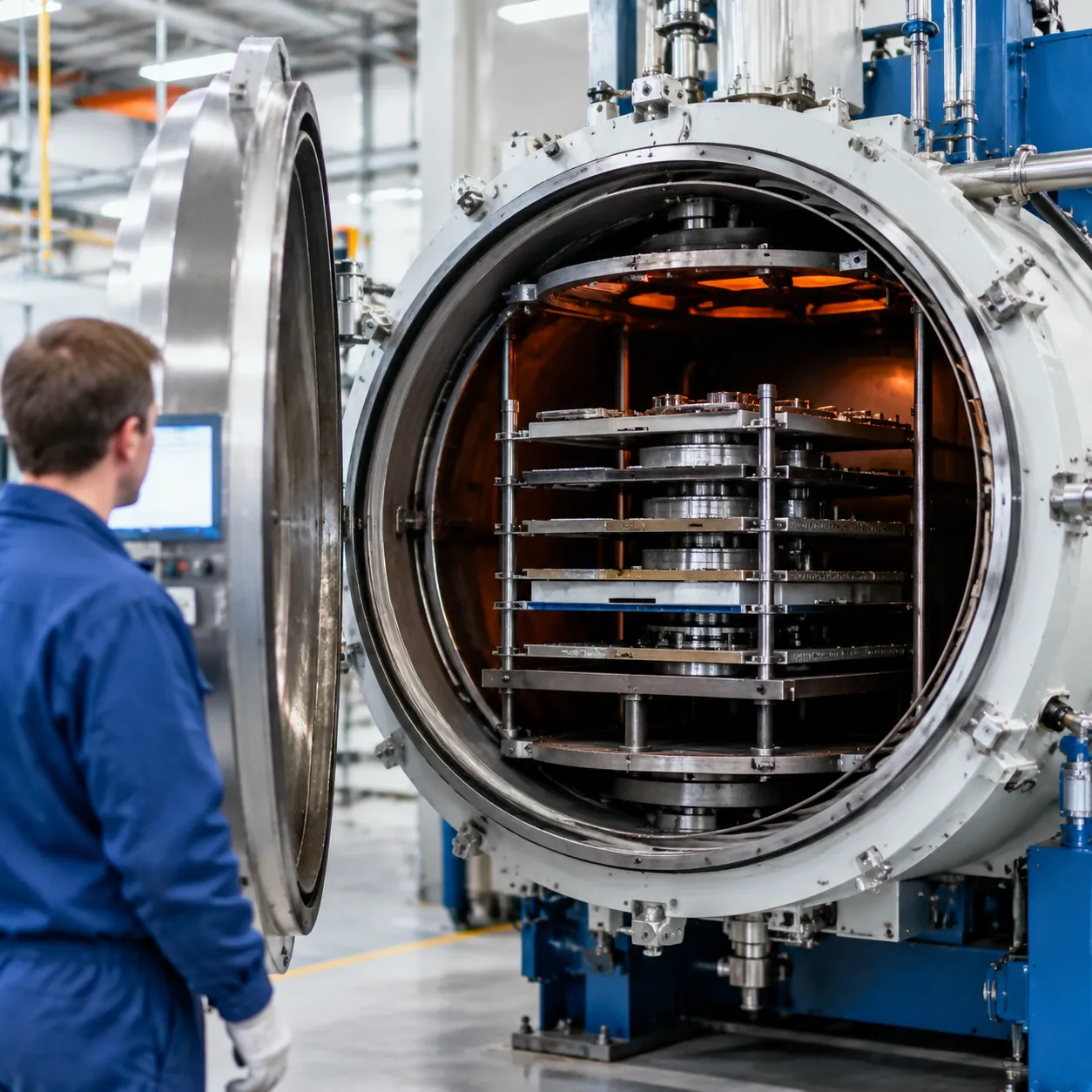
Aerospace Components and Leak-Tight Assemblies
Aerospace applications demand zero-defect joining without chemical contamination. We utilize tailored vacuum brazing furnace cycles to process high-stress assemblies:
Turbine Vanes and Fuel Nozzles: High-temperature nickel and cobalt alloys require exact thermal soak times to ensure complete filler flow and structural integrity.
Flight-Critical Heat Exchangers: Thin-walled stainless steel structures joined cleanly without flux entrapment, guaranteeing leak-tight performance under severe pressure.
Medical Device Manufacturing and Clean Precision Joints
Biocompatible components require immaculate, oxide-free surfaces. A clean vacuum furnace brazing cycle guarantees pristine joints without post-braze chemical cleaning for:
Surgical Tools and Endoscopes: Delicate micro-assemblies joined with high dimensional accuracy and zero distortion.
Medical Implants and Sensors: Titanium and stainless steel assemblies bonded under strict high vacuum heat treatment conditions.
Electronics Cooling Plates and Thermal Management
Effective heat dissipation relies on void-free brazed interfaces across liquid cold plates and heat sinks.
High-density cooling plates used in semiconductor manufacturing demand maximum thermal conductivity and leak-proof fluid channels.
Power electronics enclosures rely on precise vacuum furnace temperature control to prevent substrate cracking during cooling.
Automotive and Power Systems Heavy-Duty Joints
High-volume automotive and energy components require repeatable processing combined with high-pressure gas quenching in brazing furnace setups.
EGR Coolers and Turbochargers: Stainless steel heat exchanger cores subjected to aggressive thermal cycling.
Power Generation Hardware: Heavy-section copper and steel busbars joined with optimized vacuum furnace brazing cycle parameters.
Industrial Tooling and Precision Hardware
Industrial cutting tools and wear parts rely on exact vacuum brazing process steps to bond dissimilar metals and ultra-hard materials.
Carbide and Diamond Tooling: Fastening tungsten carbide inserts onto steel tool bodies without residual stress or joint cracking.
Specialized Ceramic-to-Metal Seals: Precision assemblies engineered to meet demanding ceramic manufacturing standards for severe-service valves and sensors.
Why Process Stability and Equipment Design Matter
Long-Term Process Repeatability
Furnace geometry, hot zone insulation, and vacuum sealing directly dictate cycle consistency. Over extended operations, minor hardware degradation can lead to uneven heating or vacuum leaks.
-
- Hot Zone Integrity: High-purity graphite or all-metal shielding prevents heat loss and maintains uniform zone temperatures.
- Leak-Tight Chambers: Double-walled, water-cooled vacuum chambers eliminate atmospheric air ingress and outgassing.
- Stable Heating Elements: Strategic element placement ensures balanced radiant heat transfer without localized hot spots.
Eliminating Batch-to-Batch Variation
Inconsistent thermal profiles compromise joint integrity, increase reject rates, and waste high-value filler metals. Precision automation keeps every vacuum furnace brazing cycle strictly within tolerance.
| Design Feature | Technical Impact | Operational Benefit |
|---|---|---|
| Multi-Zone PID Control | Synchronizes heating rates across complex workloads | Prevents part distortion and uneven braze flow |
| Real-Time Data Logging | Tracks pressure, ramp rates, and soak times | Guarantees full process traceability for QA |
| Automated Gas Quenching | Delivers rapid, uniform cooling using inert gases | Optimizes grain structure and shortens cycle times |
Through tailored design engineering, equipment configurations can be customized to match exact component dimensions and thermal load requirements.
Supporting Custom Thermal Performance
Different base metals and complex geometries demand specialized vacuum levels and heating curves. Standard off-the-shelf equipment often struggles when joining reactive alloys or tight-clearance assemblies.
-
- Tailored Heating Curves: Configurable multi-stage ramp and soak programming tailored to specific braze filler alloys.
- Flexible Atmosphere Management: Precise control over high-vacuum pumping and partial-pressure gas injection.
- System Integration: Combining hardware controls and automated software through robust process integration ensures seamless operation across demanding industrial workflows.
FAQ: Vacuum Furnace Brazing Cycle
How long does a vacuum furnace brazing cycle take?
A complete vacuum furnace brazing cycle typically ranges from 4 to 12 hours. Total time depends on load mass, component thickness, required vacuum depth, and cooling protocols. The process incorporates distinct stages:
Pump-down & Evacuation: 30–90 minutes
Ramp & Pre-heat Soaks: 1–3 hours
Brazing Soak (Peak Temp): 5–30 minutes
Forced Gas Quenching: 1–3 hours
What vacuum level is needed for brazing?
Most industrial alloys require a high-vacuum range between 10⁻³ Torr and 10⁻⁵ Torr (10⁻³ to 10⁻⁵ mbar). Standard stainless steels and nickel alloys run reliably around 10⁻⁴ Torr, while reactive metals like titanium demand deeper vacuum levels to eliminate outgassing and contamination.
What is the ideal brazing temperature?
The target brazing soak temperature is typically set 25°C to 50°C (45°F to 90°F) above the liquidus point of your chosen braze alloy. This gives the filler metal sufficient fluidity for optimal capillary action without damaging the base metal structure.
Why is temperature uniformity important?
Strict temperature uniformity ensures all joint areas across the load reach the filler alloy's melting threshold at the exact same time. Uneven thermal distribution leads to:
Premature filler flow or uneven capillary draw
Part warping and thermal distortion
Inconsistent joint strength across large batches
Can multiple parts be brazed in one cycle?
Yes, batch processing is a primary advantage of vacuum brazing. By using optimized load spacing and custom thermal engineering, our custom vacuum furnace solutions maintain uniform radiant heating across dense component arrangements.
What gases are used for cooling?
High-purity argon or nitrogen (99.999% purity) are standard for rapid forced cooling. Utilizing a high-pressure gas quench vacuum furnace rapidly drops part temperatures below critical reaction points while protecting joint brightwork.
How do I prevent oxidation during brazing?
Preventing surface oxidation requires eliminating atmospheric oxygen before heating:
Achieve precise vacuum pressure before ramping heat.
Rigorously degrease and pre-clean parts prior to loading.
Use inert cooling gases free of moisture or trace oxygen.
What causes poor brazed joint quality?
-
- Incorrect Joint Clearance: Trapping gas or failing to draw filler metal (ideal clearance is usually 0.025 mm to 0.1 mm).
- Surface Residuals: Oils, oxides, or cutting fluids blocking filler wetting.
- Insufficient Soak Time: Core sections failing to reach peak braze temperature.
- Vacuum Leaks: Ingress of air causing discoloration and joint voiding.
Related Sources
- https://www.vfe.co.uk/en/knowledge/newsdetailpage_2432.html
- https://ipsenglobal.com/introduction-to-vacuum-aluminum-brazing/
- https://www.aalberts-st.com/processes/vacuum-brazing/
- https://www.secowarwick.com/en/products/vacuum-heat-treatment/vab-technology/
- https://www.bodycote.com/what-we-do/metal-joining/furnace-vacuum-brazing/