Formula details
Product Details
Overview
Roller Kiln Customization Scope and Thermal Architecture
Uneven temperature cross-sections, unpredicted body shrinkage, roller sagging, and soaring gas bills stem from a single flaw: operating standardized equipment on specialized thermal cycles. Off-the-shelf furnaces force your product to adapt to the kiln. Our approach to roller kiln customization flips that equation—we engineer the thermal architecture entirely around your chemistry, throughput targets, and factory envelope.
Bespoke Design Based on Shrinkage and Thermal Curves
Every material tells a different story during firing. We design your continuous roller hearth furnace using empirical dilatometry data, differential thermal analysis (DTA), and mass-loss metrics.
-
- Shrinkage Compensation: We graduate roller pitch, transmission gear ratios, and cross-sectional clearances to eliminate product jamming and surface scratching as the ware shrinks.
- Degassing Windows: Low-temperature burnout zones are sized precisely to evacuate binders and organic volatiles without bloating the green body.
- Creep and Deformation Control: Roller centers and support spans are calculated based on your maximum firing temperatures and product mass per square meter.
Multi-Zone Thermal Profile Engineering
Achieving uniform density and crystal structure requires strict boundary separation between firing phases. We divide the tunnel into independently monitored and regulated zones:
| Thermal Zone | Temperature Range | Engineering Focus | Primary Mechanics |
|---|---|---|---|
| Preheating & Debinding | Ambient to 800°C | Volatile evacuation & uniform heat absorption | High-velocity recirculating burners, under-roller draft |
| High-Fire Sintering | 800°C to 1750°C | Isothermal soak, phase transformation | Staggered top/bottom firing, digital proportional control |
| Rapid Quench | 1750°C down to 900°C | Locking in microstructure, freeze phases | High-volume cold air injection with balanced exhaust |
| Slow/Final Cooling | 900°C to Discharge | Thermal shock mitigation, waste heat harvest | Counter-flow ambient air recovery modules |
Heating System Configurations
Our bespoke industrial kiln manufacturing covers three primary heating technologies configured to balance operational expenditure against product purity:
-
- Direct-Fired Gas Systems: High-velocity proportional burners mounted in staggered top-and-bottom layouts. This configuration breaks boundary air layers and delivers exceptional cross-sectional temperature uniformity (within ±2°C).
- Radiant Tube Systems: Gas-fired metallic or silicon carbide (SiSiC) radiant tubes that shield sensitive workpieces from combustion direct impingement and flue gas sulfur contamination.
- Electric Resistance Elements: Silicon carbide, molybdenum disilicide (MoSi2), or heavy-gauge FeCrAl coils for applications demanding zero emissions, ultra-pure chamber environments, and ultra-precise power ramping.
Atmosphere Management: Oxidizing, Inert, and Reducing
Consistent metallurgy and mineralogy depend on strict atmospheric separation. We engineer physical and pressure barriers within the kiln tunnel to support diverse firing chemistry:
-
- Atmospheric Seals: Adjustable baffle doors and high-velocity curtain air knives prevent atmospheric bleed between adjacent zones.
- Nitrogen and Argon Purging: Sealed roller pass-through modules with multi-stage gas purging rings keep residual oxygen levels below 10 ppm for non-oxide ceramics and battery materials.
- Reducing and Carburizing Cycles: Precision-metered injection ports introduce natural gas, forming gas, or hydrogen mixes with automated pressure equilibrium manifolds to eliminate back-draft hazards.
Chamber Sizing and Modular Expansion
Factory layouts evolve, and your thermal equipment must adapt. We build every customized roller kiln in rigid, pre-assembled modular sections:
-
- Custom Clearances: Usable roller setting widths from 600 mm to 3,800 mm, with vertical clearances tailored to your product carrier or sagger height.
- Modular Transport Frames: Factory pre-piped, pre-wired, and pre-lined sections bolt together on site, slashing commissioning lead times by up to 40%.
- Scalable Production: Plug-in module designs allow our engineers to lengthen the heating or cooling tunnels directly on your factory floor when capacity demands increase.
Drive Systems and Component Engineering for Custom Roller Kilns
Mechanical failures inside a continuous kiln almost always trace back to two culprits: transmission vibration and roller deflection under load. When a drive jerks or a roller sags under peak operating temperatures, products jam, crack, or suffer surface defects. As part of our roller kiln customization process, we engineer drive trains and core thermal components to match your precise payload weight, cycle timing, and atmosphere demands.
Precision Transmission and Variable Speed Zoning
Smooth, jitter-free product movement protects green ware and thin substrates from micro-fractures. We tailor drive configurations to eliminate backlash across every heating module:
-
- Precision Bevel Gear Drives: Enclosed, oil-bath bevel gear systems deliver zero-slip mechanical reliability for heavy payloads and ultra-wide kilns.
- Continuous Chain Loops: Segmented chain drives offer cost-effective, durable operation for medium-duty firing cycles, featuring quick-tensioning brackets for low maintenance.
- Multi-Servo Automated Drive Systems: Individual servo motors synchronize zones electronically. This setup allows independent speed profiles across debinding, peak soaking, and fast-cooling sections, giving you exact control over product retention times without mechanical reconfiguration.
Engineered Roller Selection Matrix
Matching the correct roller material to specific temperature thresholds prevents sag and catastrophic thermal shock. Our custom builds utilize high-performance refractory ceramic rollers engineered for industrial loads:
| Roller Material | Max Temp Rating | Bending Strength | Primary Applications |
|---|---|---|---|
| Heat-Resistant Alloys (Cr-Ni) | Up to 950°C | High impact resistance | Low-temp debinding, preheating, and final exit cooling zones |
| High-Purity Alumina (75–99%) | Up to 1450°C | Excellent creep resistance | Technical ceramics, structural clay, and sanitaryware |
| Reaction-Bonded SiSiC | Up to 1380°C | Extreme thermal shock & load tolerance | Heavy porcelain slabs, rapid firing, and high-density loading |
| Recrystallized SiC (RSiC) | Up to 1650°C | Maximum structural rigidity at peak temp | Advanced electronic substrates and specialized technical ceramics |
Refractory Lining Architecture
Thermal inertia directly impacts fuel consumption and temperature responsiveness. We build kiln wall and roof assemblies using a balanced composite approach:
-
- Low Thermal Mass Ceramic Fiber Modules: High-density, folded polycrystalline or ceramic fiber blankets form the hot face in fast-cycling kilns. They store minimal heat, allowing rapid heat-up and cool-down cycles while slashing energy draw.
- Insulating Firebrick (IFB) Hot Face: For corrosive atmospheres, heavy particulate generation, or high mechanical wear zones, we line chambers with precision-machined lightweight IFB. Backed by microporous insulation boards, this composite design keeps shell temperatures safely below 60°C, lowering ambient factory heat loads.
Automation, Safety, and Energy Recovery Systems
Multi-Zone Closed-Loop Temperature Control
Maintaining razor-sharp thermal stability across long kiln lengths requires granular zoning. We engineer our continuous firing platforms with independent heating and cooling sections managed via industrial PLC and SCADA network architectures:
-
- Zoned PID Regulation: Each thermal zone utilizes dedicated thermocouple arrays tied to fast-acting thyristor units (for electric elements) or modulating air-gas ratio valves.
- SCADA Supervision: Plant operators track real-time thermal curves, atmosphere pressure differentials, and drive speeds through unified graphical interfaces with historical data logging.
- Dynamic Curve Adjustments: While specialized batch operations rely on fixed schedules detailed in a vacuum brazing furnace temperature guide, continuous roller kilns demand dynamic, feed-forward loop adjustments to balance heat absorption across shifting production volumes.
Roller Protection Protocols and Mechanical Failsafes
Ceramic and alloy rollers warp rapidly if motion stops while the kiln remains hot. Our bespoke industrial kiln manufacturing integrates multi-tiered failsafes to guarantee continuous movement and physical kiln integrity:
| Protection System | Activation Mechanism | Primary Engineering Function |
|---|---|---|
| Emergency Auxiliary Drive | Auto-transfer switchgear to backup generator or DC battery banks | Keeps rollers turning instantly during utility grid loss to eliminate roller sagging. |
| Pneumatic Auto-Lift Modules | Solenoid-actuated mechanical lifters triggered by thermal thresholds | Lifts high-value loads off critical hearth sections during emergency line stoppages. |
| In-Line Broken Roller Detectors | Non-contact optical sensors and rotation pulse encoders | Flags sheared or cracked rollers in real time before downstream jams cause refractory damage. |
| Thermal Expansion Joints | Spring-loaded mechanical bellows and modular expansion gaps | Absorbs longitudinal shell expansion, preventing structural stress cracking along the kiln bed. |
Kiln Waste Heat Recovery System Integration
Direct exhaust venting wastes valuable thermal energy. We build high-efficiency heat exchangers directly into the kiln exhaust ductwork and rapid-cooling exhaust zones to slash net energy draw:
-
- Combustion Air Preheating: Captured clean hot air is routed directly back into custom high-velocity burners, preheating incoming combustion air up to 450°C and reducing natural gas consumption by 15% to 25%.
- Upstream Dryer Cascading: Excess low-grade waste heat is diverted through insulated bypass ducting into pre-kiln dryers or green-body staging zones, cutting factory-wide utility demands without auxiliary burners.
- Variable Exhaust Balancing: Automated draft dampers continuously tune kiln chamber pressure, preventing cold air ingress and stopping heat leakage around roller entrance seals.
Industry-Specific Roller Kiln Customization Profiles
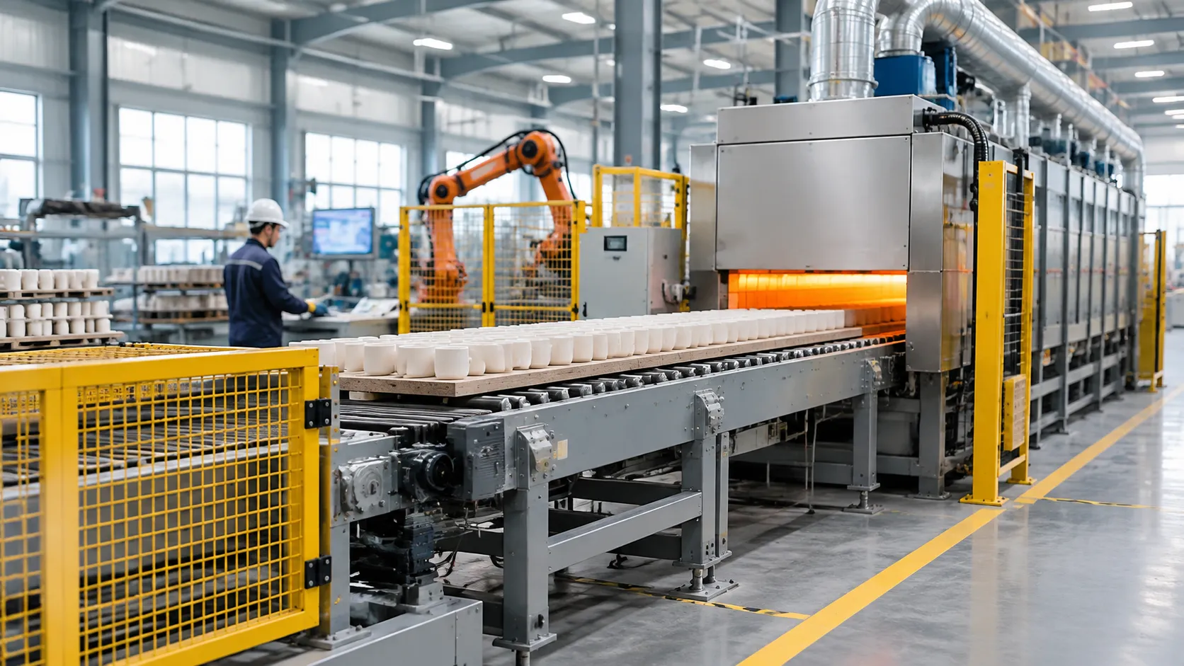
Every material behaves differently under heat. Off-the-shelf equipment frequently causes hot spots, mechanical strain, warped parts, and inflated energy bills. We engineer tailor-made thermal solutions to match specific material chemistries, mechanical loads, and plant throughput requirements. Through targeted roller kiln customization, we match drive dynamics, chamber geometry, and heating configurations directly to your target products.
| Industry Sector | Primary Product Types | Critical Custom Engineering Features | Roller Material Spec |
|---|---|---|---|
| Technical Ceramics | Alumina/AlN substrates, chip packages, dental zirconia | Ultra-tight cross-section balance (±2°C), closed-loop electric zones | High-purity Al₂O₃ (>99.5%) |
| Energy Materials | Lithium cathode powders (LFP, NCM) in saggers | Gas-tight seals, oxygen/nitrogen atmosphere control, corrosion venting | SiSiC / Recrystallized SiC |
| Architectural Surfaces | Large-format porcelain slabs, technical pavers | Wide-body chambers (up to 3.85m), high load-bearing roller drive loops | Hyper-duty mullite & SiC |
| Powder Metallurgy | Sintered gears, automotive compacts, soft magnets | Integrated debinding (RTO integration), reducing atmosphere locks | Heat-resistant alloy / SiSiC |
Advanced Technical Ceramics: Electronic Substrates and Dental Blanks
Thin electronic substrates and dense zirconia dental pucks cannot tolerate thermal gradients or micro-vibrations during the sintering stage.
Precision Temperature Control: We apply distributed electric heating elements across multiple micro-zones to deliver cross-sectional tolerances within ±2°C.
Vibration-Free Drive Trains: Direct-coupled servo drives eliminate gear backlash, preventing thin ceramic tapes from micro-cracking during transport.
Cleanroom Thermal Profiles: Pure alumina ceramic rollers and high-purity fiber linings eliminate airborne particulate contamination throughout the hot zone.
Battery Material Manufacturing: Continuous Cathode Calcination
Continuous calcination of lithium-ion cathode precursors requires handling aggressive chemical off-gassing and corrosive lithium vapor.
Atmosphere Containment: Precision gas locks and purged entry/exit vestibules maintain clean dry-air or pure-oxygen environments while conserving process gas.
Corrosion-Resistant Linings: We use dense, non-reactive cordierite-mullite hearth components and sealed silicon carbide roller furnace sections to resist alkali vapor attack.
Automated Sagger Handling: Multi-tier return loops, automated sagger de-stacking, and synchronized roller indexing ensure smooth transfer of continuous powder charges.
Architectural Surfaces: Large-Format Porcelain Slabs
Firing ultra-wide ceramic slabs up to 1600mm x 3200mm demands high mechanical support across wide hearth spans.
Anti-Deflection Roller Arrays: We calculate roller diameter-to-span ratios using heavy-duty refractory ceramic rollers to prevent sagging under high-temperature loads.
Cross-Sectional Heat Balancing: High-velocity burners fire above and below the roller plane, preventing slab edges from cooling faster than cores to eliminate warping.
Fast-Firing Modules: High-volume cooling sections lock in the mineral phase quickly, cutting cycle times while preserving flat dimensions.
Powder Metallurgy: Controlled Debinding and Continuous Sintering
Handling structural metal parts continuously requires removing organic binders cleanly before high-temperature sintering begins.
Two-Stage Thermal Processing: Our designs isolate the low-temperature debinding zone from the sintering zone to burn out binders cleanly and vent vapors straight to afterburners.
Atmospheric Protection: Nitrogen and hydrogen atmosphere barriers protect green parts from oxidation throughout heating and cooling cycles. While high-mix low-volume operations often rely on batch vacuum furnace applications, our continuous roller hearth systems deliver higher hourly throughput for standardized, high-volume production lines.
Rapid Cooling Zones: Sealed cooling jackets manage part cooling rates, helping operators achieve precise metallurgical microstructures and hardness levels.
Engineering and Commissioning Workflow for Bespoke Roller Kilns
Initial Consultation: Dilatometry Analysis, Green Body Evaluation, and Plant Footprint Review
Every successful installation begins by understanding your exact thermal chemistry and operational footprint:
-
- Dilatometry and Thermal Analysis: We test raw material shrinkage, mass loss, and phase transformations to identify critical firing and cooling rates.
- Green Body Evaluation: Analyzing green strength, organic binder burn-out behavior, and moisture levels dictates heating zone length and exhaust requirements.
- Plant Footprint Integration: Our team maps your available shop floor, utility connections, loading docks, and upstream/downstream automation to optimize traffic flow and structural clearance.
Computational Modeling: CFD Airflow Simulations and Thermal Loss Calculations
Before cutting steel, our engineers build a comprehensive digital twin of your kiln:
-
- Computational Fluid Dynamics (CFD): We model burner velocity, gas flow, and exhaust dynamics to eliminate stagnant hot spots and maintain uniform atmospheric distribution across the entire roller table.
- Thermal Loss Calculations: Finite element modeling allows us to optimize refractory wall thickness, shell skin temperatures, and hot-face interface designs, validating key roller hearth furnace advantages for efficient heating before production starts.
Precision Fabrication: Modular Frame Welding and Shop-Floor Refractory Pre-Lining
Kiln construction takes place in our controlled manufacturing environment to guarantee strict structural integrity:
| Process Step | Engineering Focus | Quality Check |
|---|---|---|
| Frame Welding | Modular, heavy-gauge steel framework with thermal relief joints | Laser alignment within ±0.5 mm |
| Refractory Pre-Lining | Interlocking low thermal mass ceramic fiber modules and insulating brick | Compression check and joint seal inspection |
| Drive Mounting | Rigid machining of drive-gear and bearing support beds | Precision leveling to prevent roller eccentricity |
Factory Acceptance Testing (FAT): Drive Synchronization and Cold-Test Verification
We verify every critical sub-system prior to crating and shipping to minimize on-site setup delays:
-
- Roller Synchronization: Continuous cold-testing confirms multi-zone variable drives rotate smoothly with zero mechanical backlash or speed differentials.
- Burner and Control Validation: Testing the full PLC control logic, flame supervision safety loops, pneumatic actuators, and safety interlocks.
- Sensor Calibration: Verifying thermocouple response times and signal paths to our master SCADA interface.
Site Erection and Commissioning: Heat Dry-Out, Thermal Curve Optimization, and Operator Training
Our field service technicians manage on-site installation, bringing the line up to full operating capacity without operational headaches:
-
- Controlled Refractory Dry-Out: We execute a programmed multi-stage dry-out schedule to purge residual moisture safely without cracking the lining.
- Thermal Curve Optimization: Fine-tuning burner staging, atmosphere pressures, and variable frequency drives under actual production loads to hit precise product density targets.
- Hands-on Operator Training: We train your maintenance and production crews on mechanical roller replacements, routine drive service, and recipe programming for complete day-to-day operational independence.
Baseline Specifications for Roller Kiln Customization
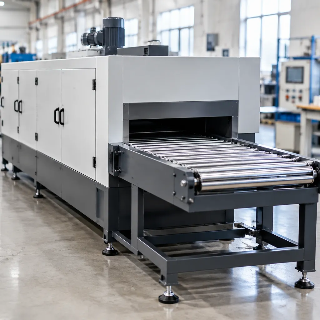
Chamber Dimensions and Clearance Thresholds
We configure the firing tunnel to fit your exact factory footprint and part geometries, ensuring smooth transit without bottlenecking:
-
- Effective Chamber Width: 600 mm to 3,850 mm (configured for single-tile passes, multi-lane saggers, or large-format slabs)
- Total Kiln Length: 15 m to 250+ m via bolted, pre-aligned modular sections
- Vertical Clearance (Above Rollers): 50 mm to 450 mm, tailored to minimize dead air volume and lower continuous energy consumption
- Working Height: Standard 900 mm to 1,150 mm centerline from plant floor level for seamless integration with automated loading cars
Thermal Performance and Uniformity
Uniform heat transfer across the entire setting width prevents warpage and phase inconsistencies in sensitive bodies:
-
- Maximum Operating Temperature: Up to 1,350°C for standard refractory lines; up to 1,600°C for high-purity technical ceramic and advanced structural lines, matching standards set by our standalone high-temperature sintering furnace systems
- Cross-Section Temperature Uniformity: ±3°C to ±5°C in soak zones through high-velocity circulation and balanced flue extraction
- Cooling Velocity Control: Multi-stage direct and indirect cooling zones reaching down to <80°C discharge temperatures
| Specification Parameter | Standard Base Range | Heavy-Duty / High-Temp Option |
|---|---|---|
| Max Temperature | 1,280°C | 1,600°C |
| Chamber Width | 1,200 mm – 2,600 mm | Up to 3,850 mm |
| Roller Pitch (Center-to-Center) | 50 mm – 80 mm | 30 mm – 120 mm (Variable by zone) |
| Payload Capacity | 20 – 60 kg/m² | Up to 180 kg/m² |
| Control Zones | 5 – 25 independent zones | Up to 60+ micro-zones |
| Firing Systems | Electric / Natural Gas | Dual-fuel, LPG, or Hydrogen-blend |
Mechanical Loading and Transmission Ratings
Roller sizing and spacing prevent product deflection across wide spans under load:
-
- Roller Pitch Engineering: Dense spacing (30–45 mm) in rapid-cool and soak sections prevents hot-sagging under heavy structural components; wider spacing (up to 120 mm) in preheat reduces rolling resistance.
- Transmission Design: Grouped multi-inverter frequency drives or independent servo loops, allowing zone-by-zone speed adjustments from 0.2 m/min to 8.0 m/min.
- Drive Redundancy: Continuous mechanical bevel-gear or dual-strand chain networks paired with uninterruptible battery and auxiliary generator failsafes.
Burner Configurations and Energy Sources
We tailor the combustion setup directly to your plant's utility availability and local emissions guidelines:
-
- Direct-Fired Pulse Burners: High-velocity, staggered over-and-under roller placement for natural gas or LPG, creating continuous turbulent mixing.
- Electric Resistance Elements: Silicon carbide (SiC) or MoSi₂ heating elements arranged vertically along chamber walls or horizontally over the roller plane for zero-emission cleanrooms.
- Flue and Damper Architecture: Automated draft control with individual zonal pressure transmitters to prevent cold air ingress and hold strict neutral or slightly positive chamber pressure.
Roller Kiln Customization FAQs
What data do we need to provide to start a custom roller kiln design?
To initiate the project smoothly, our engineering team requires specific product and process parameters during the initial custom furnace design and engineering review:
-
- Product specifications: Green body dimensions, weight per piece, mass per batch or sagger, and chemical profile (including volatile binder content).
- Thermal cycle: Required firing curve, peak operating temperature, minimum soak duration, and permissible heating/cooling rates (°C/min).
- Atmosphere profile: Oxidizing, inert (nitrogen), or reducing gas requirements along the length of the kiln.
- Target throughput: Daily or hourly production rates (kg/h, pieces/min, or m²/day).
- Facility utilities: Available plant footprint, ceiling clearances, electrical load capacity, and fuel sources (natural gas, LPG, or pure electric).
How do you choose between silicon carbide and alumina rollers for high loads?
Selecting the right roller material prevents sagging, product distortion, and unplanned line shutdowns. We determine the specification based on firing temperature, span width, mechanical load, and thermal shock severity:
| Feature / Metric | High-Purity Alumina Rollers ($Al_2O_3$) | Reaction-Bonded Silicon Carbide (SiSiC) |
|---|---|---|
| Max Working Temp | Up to 1,350°C (depending on load) | Up to 1,380°C (higher for recrystallized SiC) |
| Bending Strength | Moderate (150–220 MPa) | Very High (250–350+ MPa) |
| Thermal Shock | Good (requires steady preheating) | Exceptional (handles rapid cycling) |
| Load Bearing | Lighter payloads, standard kiln widths | Heavy payloads, wide spans, dense saggers |
| Typical Target | Standard ceramics, substrates, ferrite parts | Heavy technical tiles, battery saggers, slabs |
Can a single custom roller kiln handle multiple firing atmospheres?
Yes. We engineer multi-atmosphere continuous lines by integrating atmospheric separation locks and precision pressure control:
-
- Atmospheric isolation: High-velocity air or nitrogen curtains combined with refractory baffles separate debinding, sintering, and cooling segments.
- Pressure balancing: Cascaded digital pressure transmitters maintain micro-positive pressure in inert chambers to block air infiltration.
- Zoned venting: Dedicated exhaust paths vent binder burnout volatiles safely before product carriers advance into high-purity zones within our continuous roller hearth furnace systems.
How do built-in failsafes prevent roller warping during power outages?
Stationary rollers carrying hot loads will sag rapidly under extreme heat. We build redundant, automated protection into our transmission platforms:
-
- Instantaneous UPS backup: Solid-state battery backups instantly engage to maintain roller rotation without a millisecond of line stoppage.
- Automatic generator transfer: An automated transfer switch (ATS) starts an auxiliary power generator within seconds to sustain continuous rotation.
- Pneumatic or manual oscillation: If electrical systems fail entirely, a mechanical oscillating drive system rocks the rollers back and forth 90° to 180° using compressed reserve air or a manual emergency crank, maintaining dynamic load distribution until the kiln cools.
What energy savings can you expect from an integrated heat recuperation system?
An engineered waste heat recovery system directly lowers operating expenses by capturing exhaust from the fast-cooling and firing zones:
-
- Combustion air preheating: Heat exchangers preheat primary burner combustion air up to 350°C–450°C, delivering 15% to 25% net fuel savings.
- Direct hot air recovery: Clean hot air pulled from product cooling modules is ducted directly to upstream spray dryers or drying chambers, capturing an additional 5% to 10% thermal efficiency.
- Optimized shell insulation: Low-thermal-mass ceramic fiber linings reduce surface shell temperatures below 60°C, eliminating ambient thermal waste and trimming factory HVAC loads.