Fundamentals of Fluxless Vacuum Furnace Nickel Brazing
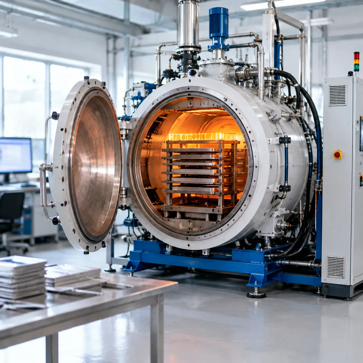
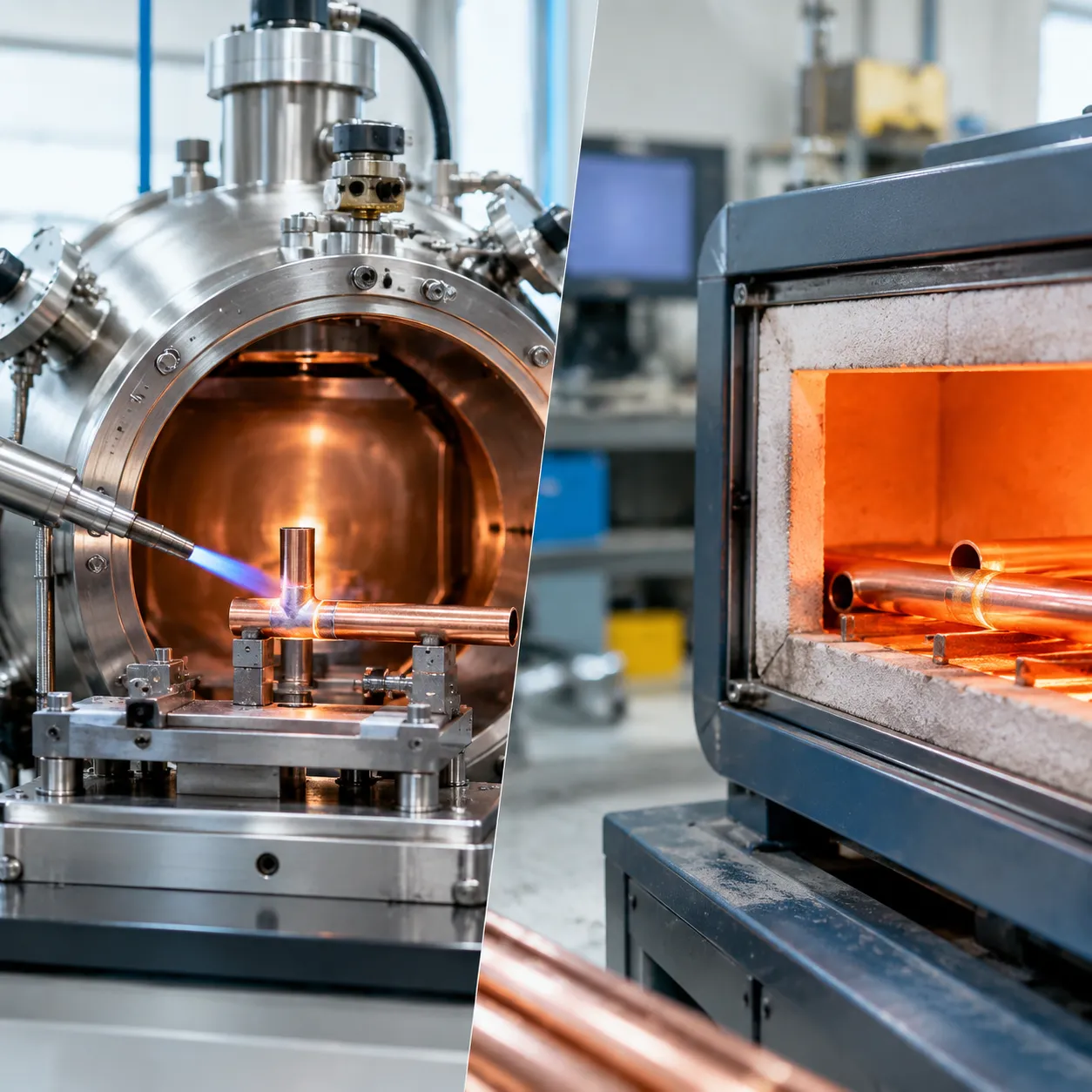
We achieve high-yield joint integrity through deep atomic diffusion across base metal interfaces rather than simple mechanical adhesion. Operating in a zero-oxidation vacuum environment completely eliminates the need for aggressive, corrosive chemical fluxes. Under high-vacuum conditions, the partial pressure of oxygen drops low enough to drive thermodynamic oxide dissociation. Chromium oxides on 304 and 316L stainless steels break down naturally at elevated temperatures, exposing pristine metallic surfaces ready for uniform wetting.
BNi Filler Metal Selection: BNi-2 vs. BNi-5 Specifications
Selecting the right nickel base filler metal dictates joint ductility, erosion depth, and operational limits. The choice between boron-bearing and boron-free alloys changes melt behavior and thermal response significantly:
| Parameter | BNi-2 (Ni-Cr-B-Si-Fe) | BNi-5 (Ni-Cr-Si) |
|---|---|---|
| Melting Dynamics | Near-eutectic response | Broad solidus-liquidus range |
| Solidus / Liquidus | 970°C / 1000°C (1780°F / 1830°F) | 1080°C / 1135°C (1975°F / 2075°F) |
| Depressant Element | Boron (B) & Silicon (Si) | Silicon (Si) only |
| Primary Application | Thin-walled structural assemblies | Nuclear & high-temperature oxidation environments |
Managing Liquidus Dynamics and Substrate Erosion
Executing successful high-temperature nickel alloy brazing requires precise control over temperature ramps to preserve substrate integrity:
-
- Eutectic Flow Control: Eutectic nickel brazing alloys flow rapidly upon reaching their brazing alloy liquidus temperature, ensuring complete capillary penetration without prolonged furnace dwell times.
- Preventing Thin-Gauge Erosion: Boron acts as a fast diffuser. Excess hold times or overheating cause boron to migrate into thin sheet substrates, causing localized melting and base metal erosion.
- Thermal Precision: Matching hold times to part mass prevents early binder outgassing failures while shielding delicate core features from base metal dissolution.
Critical Process Parameters and Joint Architecture
Precision Joint Clearance and Capillary Action
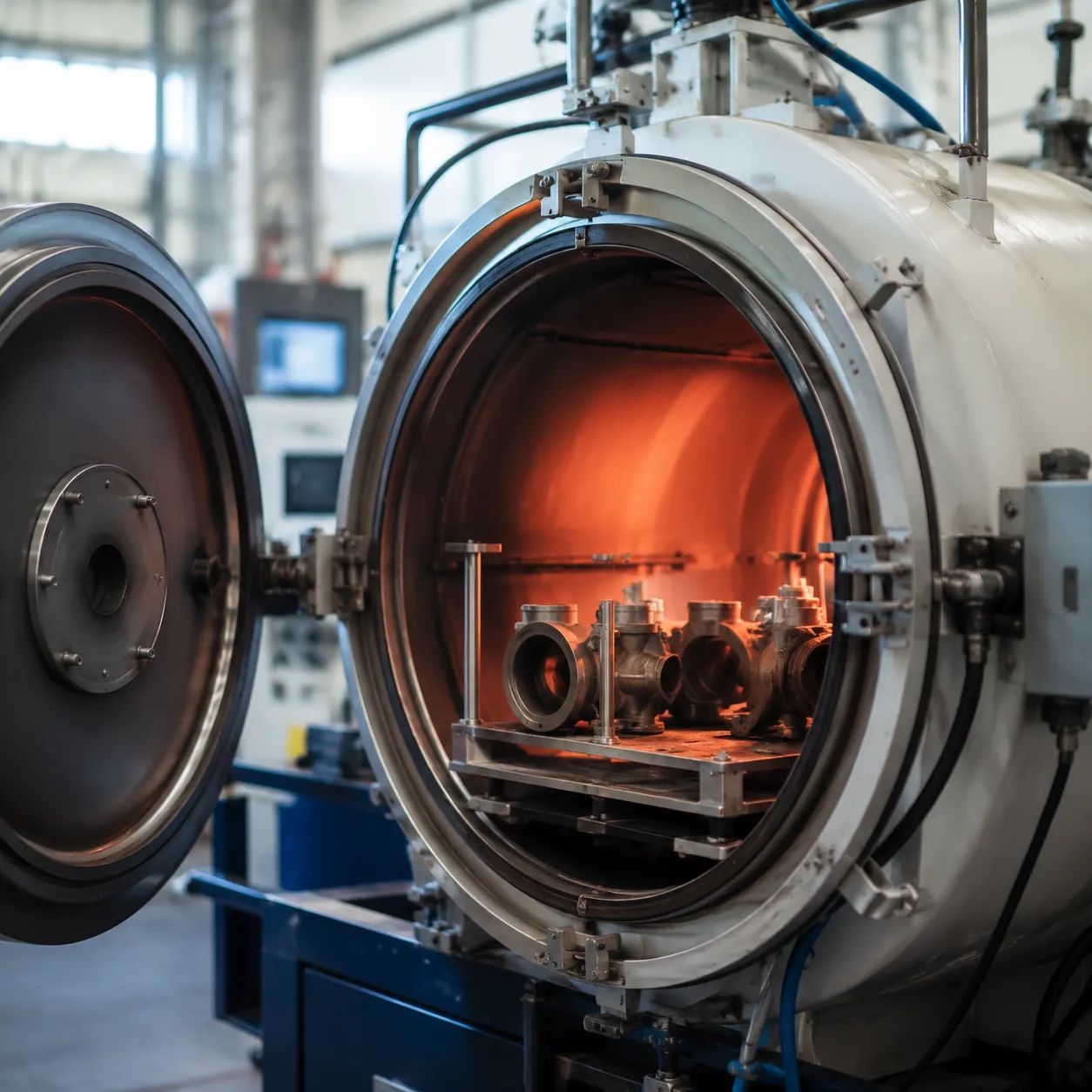
Capillary action drives filler metal distribution across the joint interface, but its efficiency depends entirely on tight tolerances. We recommend maintaining a strict brazing joint gap clearance of 0.0013" to 0.0022" (0.03 mm to 0.05 mm) at peak processing temperature.
-
- Optimal Clearance (0.03 mm to 0.05 mm): Maximizes capillary draw, ensures complete filler penetration, and provides high joint shear strength.
- Excessive Clearance (> 0.05 mm): Slows capillary flow and forms a brittle centerline intermetallic phase due to silicon or boron segregation, causing severe joint strength loss.
- Differential Thermal Expansion: When joining dissimilar metals, we calculate thermal expansion differentials in advance to ensure the gap remains within the target threshold at liquidus temperature.
Step-by-Step Vacuum Furnace Thermal Profiling
| Cycle Stage | Process Action | Operational Purpose |
|---|---|---|
| 1. Evacuation | Vacuum pump down | Clears atmospheric oxygen and residual moisture. |
| 2. Pre-Heat Soak | Thermal ramp to 800°C–900°C | Equalizes core and surface temperatures across varied cross-sections. |
| 3. Outgassing Dwell | Isothermal hold | Removes organic binders from brazing pastes without contaminating the hot zone. |
| 4. Peak Braze | Rapid ramp to 1000°C–1180°C | Ensures rapid filler flow while minimizing substrate erosion. |
| 5. Forced Gas Quenching | Pressurized inert gas cooling | Solidifies the joint rapidly and locks in target mechanical properties. |
We often run a combined brazing and heat treating cycle, performing solution annealing and stress relief in a single furnace run to streamline post-processing. You can read more about how integrated thermal cycles optimize production in our guide to vacuum furnace applications and benefits.
Overcoming Wetting Issues on Reactive Superalloys
High-temperature nickel alloy brazing on superalloys like Inconel 718 and Rene 41 presents distinct surface chemistry challenges. Aluminum and titanium content forms stable oxide films (Al₂O₃, TiO₂) that will not break down under standard vacuum levels, impairing filler wetting.
To resolve this issue, we employ targeted surface preparation techniques prior to furnace loading:
-
- Electrolytic Nickel Surface Plating: Deposits a thin, pure nickel barrier layer (0.0002"–0.0005") over the base metal, preventing oxide formation and creating a highly wettable surface.
- Fluoride-Ion Cleaning (FIC): Uses gaseous HF to strip chromium, titanium, and aluminum oxides from deep within narrow joint channels, restoring metal surface reactivity for high-integrity capillary flow.
Industrial Vacuum Furnace Design Considerations for High-Yield Brazing
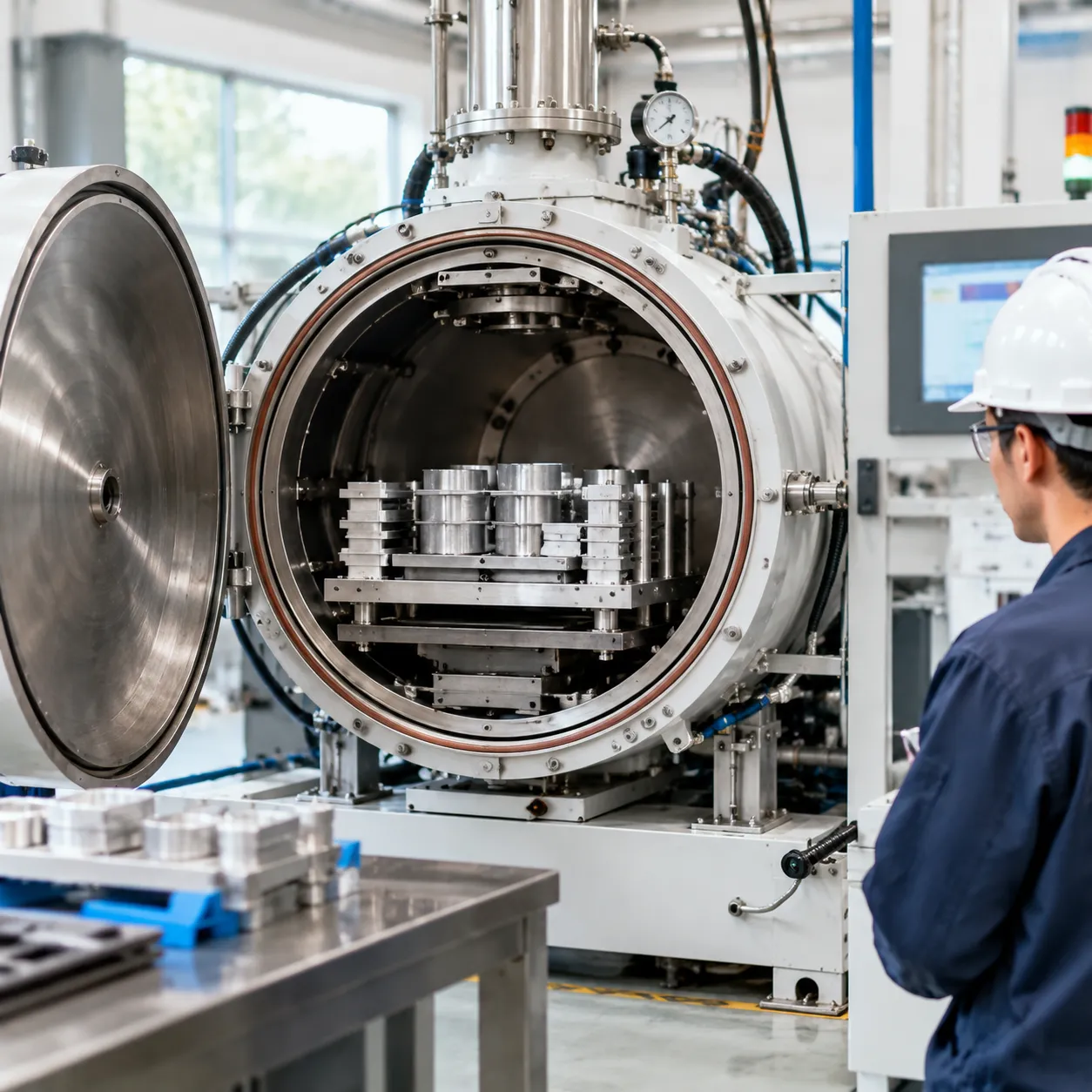
High-yield nickel brazing demands extreme atmosphere control and precise temperature management to eliminate oxidation and prevent joint contamination. We engineer our industrial vacuum brazing furnace systems to maintain high repeat accuracy under harsh operational conditions.
High-Vacuum and Dew Point Control
Running high-temperature nickel alloy brazing at 1200°C+ requires clean vacuums and minimal residual oxygen to prevent surface passivation on alloys containing chromium, aluminum, or titanium.
-
- Ultimate Vacuum Pressure: Multi-stage pumping systems achieve operating pressures down to 10⁻⁵ Pa, removing trace oxygen before heating begins.
- Dew Point Control: Maintaining a system dew point below -60°C prevents water vapor dissociation, protecting component surfaces from oxidation.
- Binder Outgassing Management: Dedicated low-temperature dwell stages (300°C to 450°C) fully burn off organic binders in brazing pastes and stop-off compounds before high-vacuum pumping.
Hot Zone Material Selection
Selecting the proper hot zone insulation and element material prevents element degradation and alloy contamination at elevated temperatures.
| Hot Zone Type | Max Operating Temp | Contamination Risk | Vacuum Cleanliness | Ideal Application |
|---|---|---|---|---|
| Molybdenum | 1350°C | Minimal | High | Stainless steel (304, 316L) & nickel superalloys |
| Tungsten | 2000°C+ | Minimal | Very High | Refractory metal joining & extreme high-temp operations |
| Graphite | 2200°C | Carbon Pick-up Risk | Moderate | Low-alloy steels; not recommended for sensitive superalloys |
For high-yield nickel alloy joining, all-metal hot zones with molybdenum heating elements deliver clean processing without the risk of carbon pick-up or microstructural joint embrittlement.
Thermal Uniformity and SCADA Automation
-
- Tight Temperature Distribution: Multi-zone heating elements achieve ±1°C thermal uniformity across heavy payload batches, preventing localized erosion or incomplete filler flow.
- Automated Thermal Profiling: Integrated Siemens or Eurotherm PLCs manage multi-stage heating ramps, outgassing dwells, peak braze timing, and forced gas quenching cycles.
- SCADA Data Logging: Real-time data acquisition logs vacuum pressure, dew point, and multi-point thermocouple readings for complete process verification and quality assurance.
Troubleshooting Common Vacuum Brazing Defects
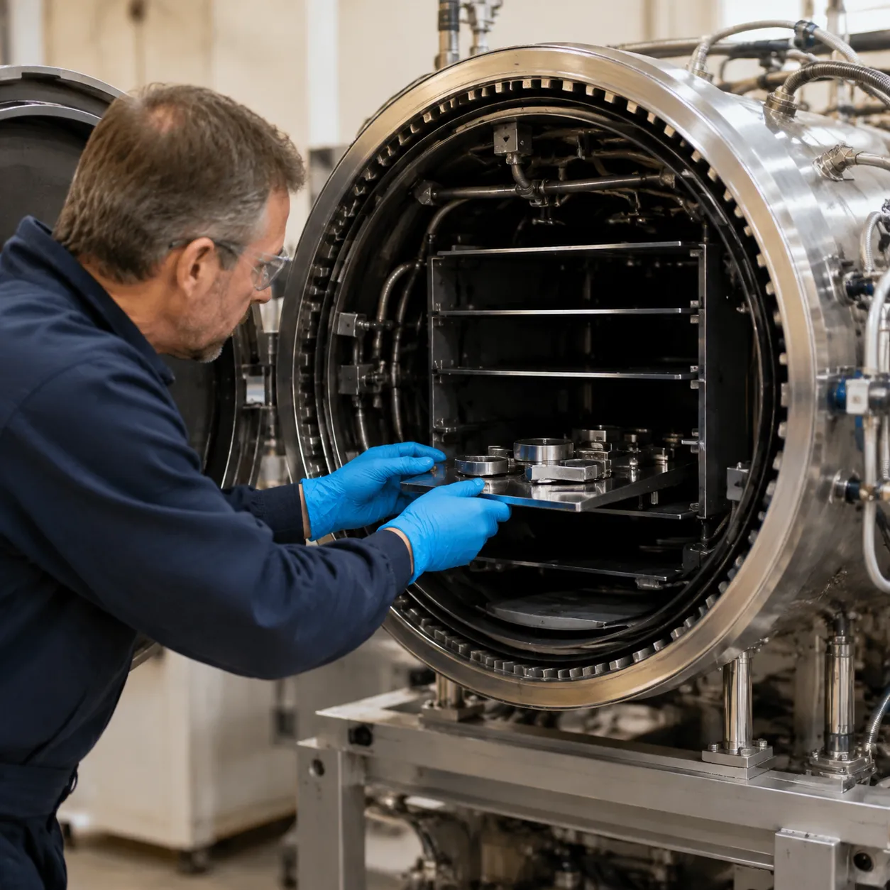
When nickel brazing in vacuum furnace systems faces quality drops, shop-floor teams usually encounter three main failure modes: incomplete wetting, brittle joints, or part distortion.
Fixing Poor Wetting and Incomplete Joint Penetration
If filler metal fails to cap or flow through the joint, atmosphere contamination or furnace leaks are typically the primary root causes. Understanding how a vacuum furnace works makes it far simpler to isolate mechanical atmosphere leaks from material outgassing.
-
- Furnace Leak Rate Diagnostics: Run a rate-of-rise leak check prior to processing high-value loads. Leak rates must remain under 5 mTorr/hour to prevent instant surface re-oxidation of chromium-bearing alloys.
- Vacuum Integrity: Maintain dynamic operating vacuum levels at or below 10⁻³ Pa. Any sudden pressure spike during peak ramp indicates active outgassing or active atmospheric air ingress.
- Pre-Brazing Cleanliness: Verify complete removal of oils, cutting fluids, and oxides using solvent degreasing or chemical pickling before assembly.
Preventing Joint Embrittlement and Microstructural Voids
Brittle centerline intermetallic phases occur when melting point depressants like boron and silicon fail to diffuse out of the joint during high-temperature nickel alloy brazing.
-
- Diffusion Dwell Times: Extend hold times at peak braze temperature to give borides and silicides enough time to diffuse into the base metal matrix.
- Joint Gap Precision: Maintain tight tolerances between 0.03 mm and 0.05 mm (0.0013" to 0.0022"). Excessively wide gaps force the filler metal to solidify as a continuous brittle eutectic core.
- Binder Management: Utilize low-residue binder systems for BNi paste formulations to prevent trapped carbon voids during rapid thermal ramping.
Avoiding Workpiece Distortion and Discoloration
Component warping and surface dullness are caused by sharp thermal gradients or inadequate vacuum purity. Balancing heat transfer in a vacuum furnace keeps thin-walled assemblies flat and metallurgically sound.
| Defect Root Cause | Immediate Floor Action | Preventive Process Adjustment |
|---|---|---|
| Thermal Stress & Warping | Reduce heating ramp rates above 800°C | Add pre-heat equalization steps to balance core-to-surface temps |
| Quench Deformation | Step down forced gas quench pressure | Program multi-stage, variable-speed gas cooling profiles |
| Surface Discoloration | Check hot zone insulation for leaks or oil carryover | Run a high-temperature empty chamber bake-out cycle |
| Outgassing Voids | Extend vacuum outgassing dwell at 450°C | Ensure complete binder burnout prior to reaching alloy liquidus |
Industrial Applications of Vacuum Nickel Brazing
Aerospace and Industrial Gas Turbines
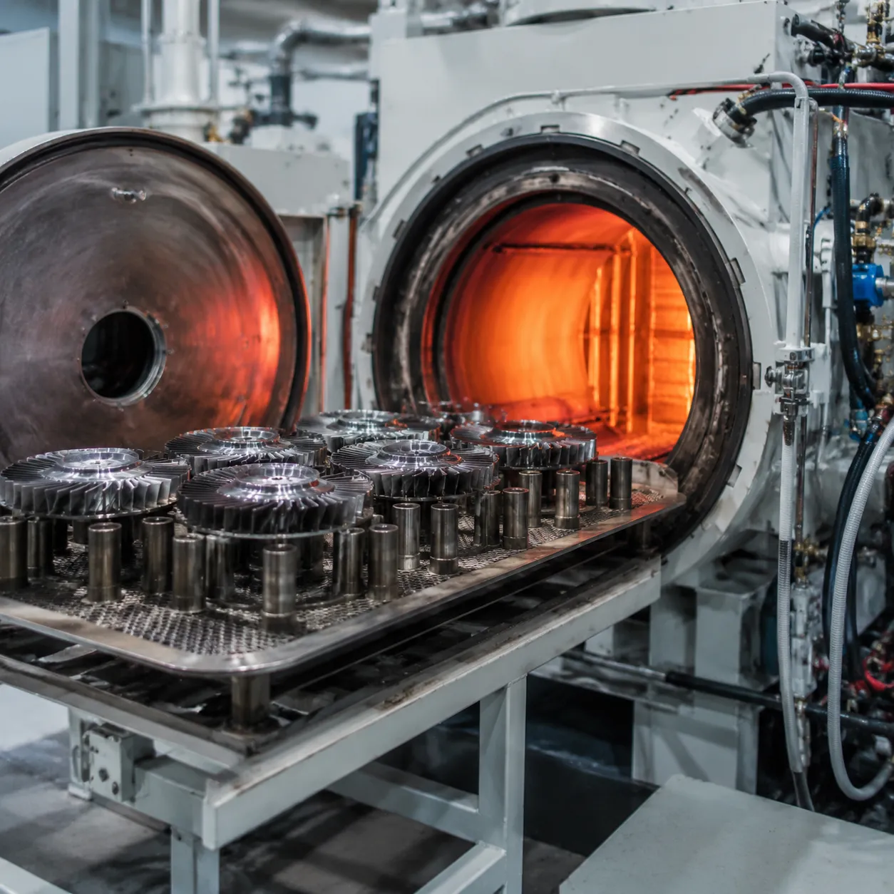
Extreme operating temperatures and cyclic stresses require flawless capillary penetration. We build vacuum processing solutions engineered for complex turbine and propulsion components:
-
- Regeneratively Cooled Nozzle Assemblies: Handles intricate internal cooling passages, guaranteeing pressure-tight seals without clogging micro-channels.
- Turbine Vanes and Stators: High temperature nickel alloy brazing maintains parent metal strength and creep resistance under hot gas path conditions.
- Flight-Critical Heat Exchangers: Thin-foil matrix designs achieve maximum heat transfer efficiency without risk of burn-through or erosion.
Automotive and Energy Infrastructure
High-volume manufacturing demands repeatability and absolute thermal control across multi-component assemblies. Utilizing advanced vacuum heat treatment furnace technology ensures zero-defect brazing for demanding energy systems:
-
- EGR Coolers: Produces vibration-resistant stainless steel joints that withstand aggressive acid condensate and continuous thermal shock.
- Plate Heat Exchangers: Keeps multi-layered brazed stacks flat, leak-free, and structurally sound across heavy production runs.
- Fuel Cell Components: Provides oxide-free joining for bipolar plates and flow channels where contamination degrades electrochemical efficiency.
Medical Devices and Chemical Processing Equipment
In ultra-clean environments, post-braze chemical residues are a liability. Vacuum processing provides pure metal joining tailored to high-purity industrial heat treatment standards:
-
- Hygienic Fluid Manifolds: Flux-free processing guarantees zero internal chemical entrapment, protecting sensitive analytical and medical fluids.
- Corrosion-Resistant Reactors: Nickel-based filler alloys yield robust chemical resistance against aggressive acids and high-pressure media.
- Surgical Instrumentation: Combines high structural joint strength with a flawless cosmetic finish straight out of the hot zone.
Elevating Production Quality with Custom Vacuum Furnaces
Custom Vacuum Furnace Specifications
We engineer each chamber around your alloy chemistry, payload mass, and cycle times:
| Parameter | Engineering Capability & Specs |
|---|---|
| Maximum Temperature | Up to 2400°C for advanced nickel superalloys and specialized thermal runs |
| Ultimate Vacuum Level | High-vacuum pumping systems achieving down to 10⁻⁵ Pa for zero oxidation |
| Thermal Uniformity | Precision multi-zone heating delivering ±1°C temperature distribution |
| Payload Capacity | Bespoke chamber designs supporting heavy loads up to 20 metric tons |
| Global Standards | Full compliance with ISO 9001 and CE quality and safety certifications |
Complete Technical Partnership and Global Support
We deliver fully integrated thermal processing systems alongside complete operational support:
-
- Turnkey Customization: Through our dedicated custom engineering services, we design custom chamber layouts, loading systems, and PLC/SCADA control systems tailored to your shop floor.
- Application Testing: Our metallurgical team helps test and validate your BNi filler metals, outgassing dwells, and ramp rates to eliminate defects before installation.
- 24/7 Global Field Service: You receive continuous technical support, direct access to spare parts, and on-site engineering assistance to maintain zero unplanned downtime.
Discover our full lineup of industrial vacuum furnaces built for high-temperature alloy processing.
Frequently Asked Questions About Nickel Vacuum Brazing
What is the ideal vacuum pressure for high-temperature nickel alloy brazing?
We recommend maintaining a high vacuum level between 10⁻³ Pa and 10⁻⁵ Pa during the peak braze cycle. High-temperature nickel alloy brazing requires a zero-oxidation atmosphere to promote wetting without flux. Keeping furnace leak rates low and ensuring dew point control below -60°C prevents chromium and titanium oxidation on sensitive alloys. Operating high-performance vacuum furnace solutions ensures reliable atmospheric purity across entire production runs.
How do you prevent boron embrittlement along the joint centerline when using BNi-2 filler metal?
Boron acts as a melting point depressant in BNi-2, but excessive accumulation forms a brittle centerline intermetallic phase. To prevent microstructural voids and joint embrittlement, we control three primary parameters:
-
- Tight Joint Clearance: Maintain precision gap tolerances between 0.0013" and 0.0022" (0.03 mm to 0.05 mm) to minimize the volume of un-diffused braze alloy.
- Extended Diffusion Dwell: Allow sufficient soak time at peak braze temperature so boron atoms fully diffuse into the parent metal matrix.
- Optimal Processing Temperature: Operate within the 1010°C to 1065°C window to accelerate interdiffusion without degrading thin base substrates.
Why is Fluoride-Ion Cleaning (FIC) required for vacuum brazing high-titanium superalloys?
Superalloys containing titanium and aluminum (such as Inconel 718, Waspaloy, or Rene 41) form tenacious surface oxides (TiO₂ and Al₂O₃) that do not dissociate under standard vacuum furnace brazing temperatures. Fluoride-Ion Cleaning (FIC) chemically strips these oxide layers and selectively depletes reactive Al/Ti atoms from the substrate surface prior to heating. For less severe alloy formulations, electrolytic nickel surface plating serves as an effective alternative barrier to restore capillary action.
Can vacuum nickel brazing and solution annealing be combined into a single thermal cycle?
Yes. Combining nickel base filler metal brazing with solution annealing into a single thermal profile saves energy, reduces turn-around times, and minimizes thermal hysteresis stress. By selecting a filler metal with a liquidus temperature matching the solution treating range of the parent alloy, we braze at peak temperature and follow immediately with overpressure forced gas quenching in our horizontal vacuum furnace systems to lock in the required metallurgical phase.
Related Sources
- http://solaratm.com/uploads/2015/06/4_brazingpdf.pdf
- https://www.vacfurnace.com/technology-frontiers/how-to-choose-a-suitable-vacuum-furnace/
- https://www.wallcolmonoy.com/company-profile/news/surface-preparation-for-high-vacuum-brazing/nicrobraznews-surface-preparation-for-high-vacuum-brazing-nov11/
- https://www.vacfurnace
- https://www.vacfurnace.com/technology-frontiers/316l-stainless-steel