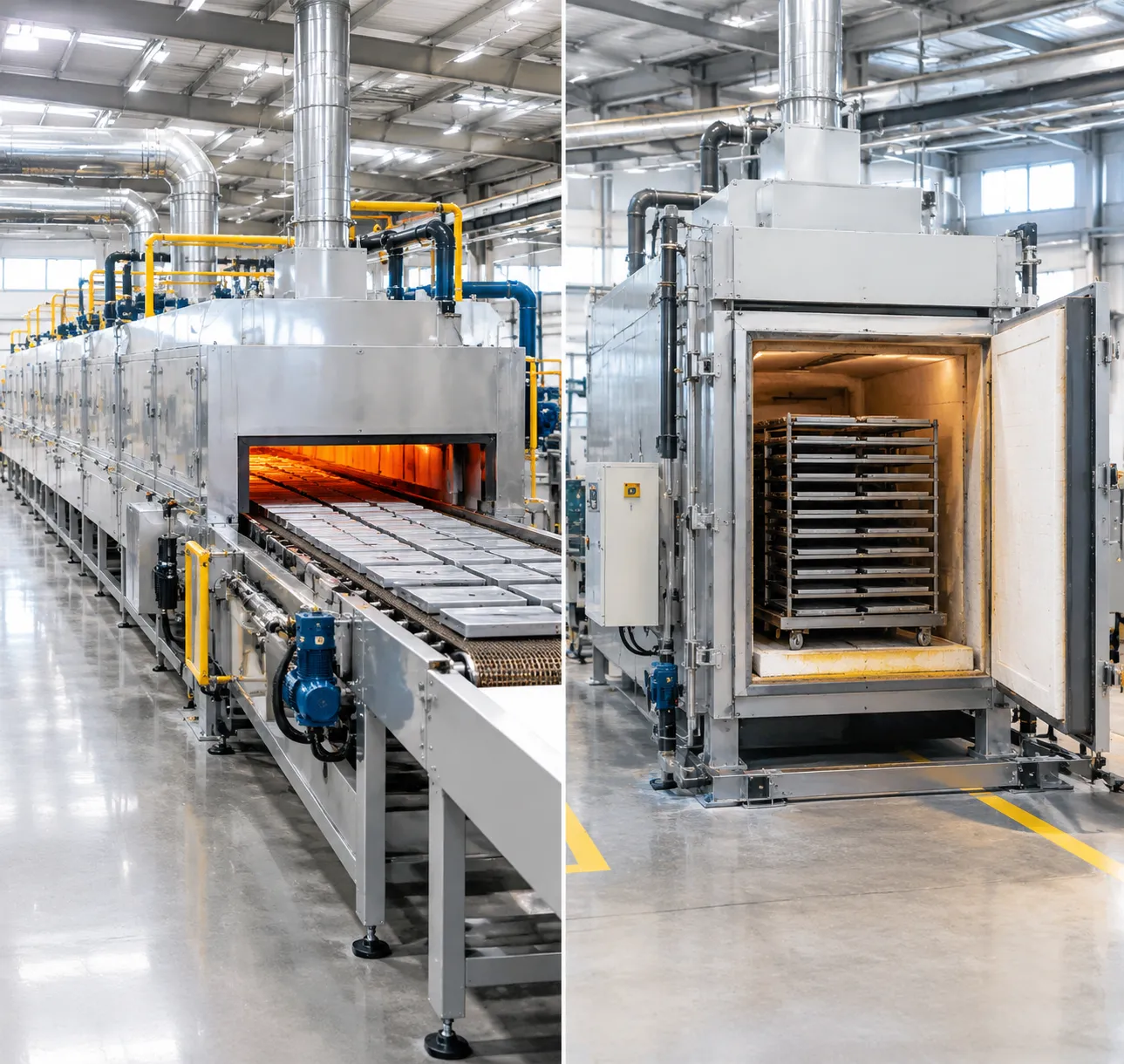
Are you struggling to decide on the right thermal processing setup for your battery production line?
Navigating the continuous vs batch furnace battery debate is a critical step that will directly impact your manufacturing throughput, energy costs, and final material quality.
Having worked closely with battery manufacturers, I know that choosing the wrong equipment can bottleneck your entire operation. That’s why I’ve put together a practical breakdown that goes beyond the basic spec sheets, using real industry experience to help you make a smart, profitable investment.
Whether you are scaling up mass production or perfecting custom cell chemistries, you are about to learn the exact pros, cons, and operational realities of each system.
Let's dive right in!
Continuous vs Batch Furnace Operating Mechanics in Battery Production
Thermal processing dictates the crystal structure, phase purity, and electrochemical performance of battery active materials. Choosing between continuous and batch thermal architectures comes down to how your facility manages material kinematics, atmosphere control, and thermal profiles during calcination.
Continuous (RHK/Pusher): Steady-State Flow ──► Zone-Specific Thermal/Gas Profiles ──► Constant Output
Batch (Box/Car-Bottom): Static Chamber ──► Cyclic Time-Temperature Profiles ──► Flexible Run Sizes
Roller Hearth and Pusher Slab Continuous Systems
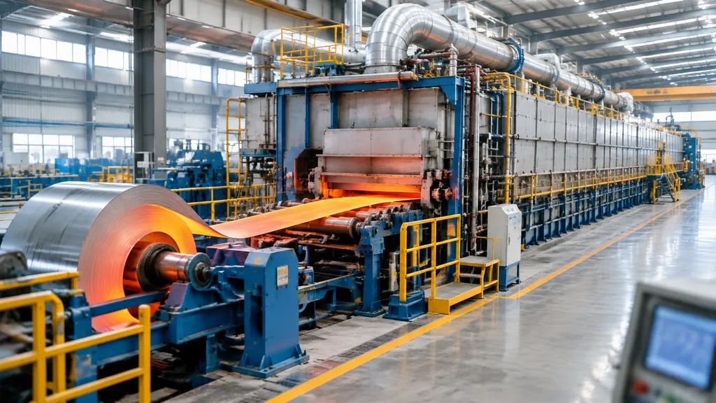
Continuous furnaces rely on dynamic, continuous material transport through fixed, sequential temperature zones:
-
- Roller Hearth Kilns (RHK): Driven ceramic rollers move stacked saggars continuously through the tunnel. They deliver low mechanical vibration, rapid cycle speeds, and minimal saggar friction, making them the standard for high-volume cathode material sintering.
- Pusher Slab Furnaces: Hydraulic or mechanical pushers advance trains of refractory slabs bearing saggars along stationary skid rails. These units handle higher payload weights per footprint than rollers, but they face higher wear on hearth plates and periodic mechanical push-rod fatigue.
Continuous systems operate at a thermal steady state. Once the kiln stabilizes at temperature, energy input balances thermal losses directly, preventing the refractory wear associated with repetitive heating and cooling cycles.
Stationary Batch Atmosphere Furnaces
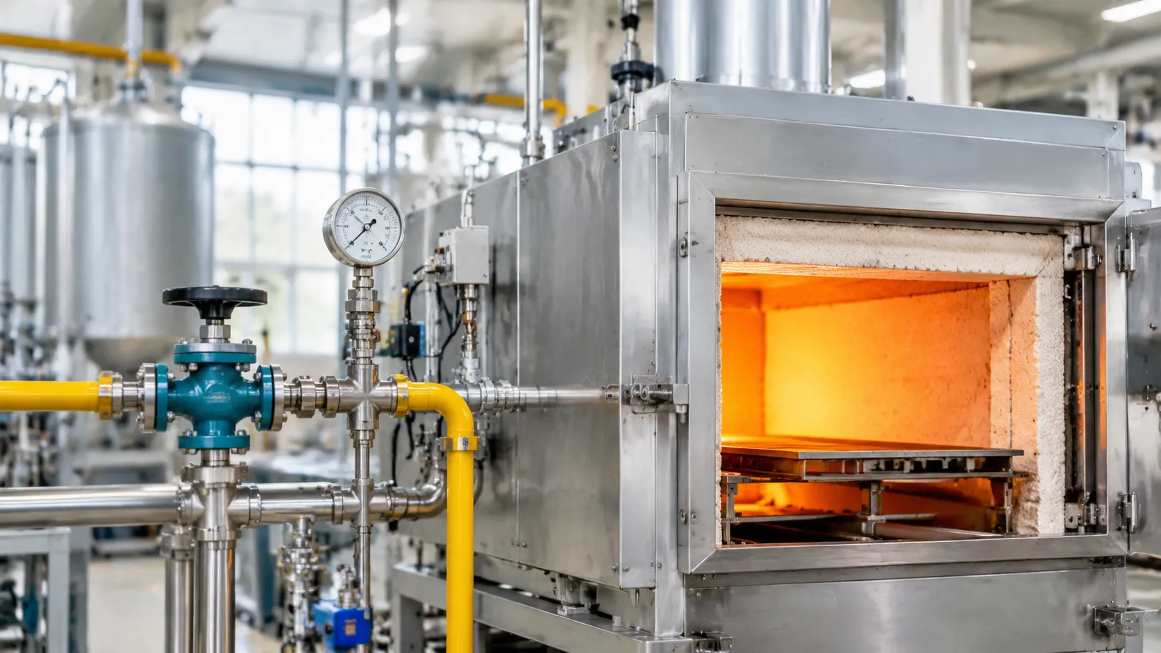
Batch atmosphere furnaces process discreet charges within an enclosed, sealed chamber:
-
- Box and Chamber Furnaces: Sealed front-loading designs optimized for small-lot cathode calcination, dopant testing, and solid-state electrolyte trials.
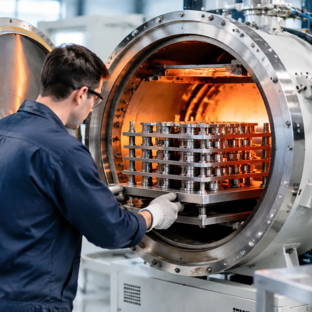
- Car-Bottom (Bogie Hearth) Kilns: Motorized hearths roll out for overhead crane or forklift loading of multi-layer saggar matrices, then seal into the furnace frame for firing.
- Pit/Retort Furnaces: Top-loading, sealed cylindrical retorts engineered for tight gas confinement during anode active material carbonization.
Batch units execute the entire firing profile—binder burnout, solid-state reaction, dwell, and cooling—within a single footprint over time rather than space.
Saggar Conveyance and Material Flow Dynamics
Material movement defines line stability and saggar life:
-
- Multi-Zone Continuous Conveyance: Automated return tracks cycle saggars through unstacking, vacuum powder dumping, cleaning, automated refilling, and restacking stations. Any mechanical misalignment or cracked saggar risks roller jams and catastrophic line downtime.
- Batch Material Handling: Relies on manual or semi-automated batch loading. While material throughput is lower, mechanical failure risks inside the hot zone drop to zero during the cycle.
- Thermal Shock Management: Continuous lines demand staged preheat zones to prevent cordierite-mullite saggar spalling. Batch furnaces introduce uniform, ramped heating rates that reduce immediate thermal shock across the saggar walls.
Purge Gas Dynamics and Exhaust Management
Managing process gas flow determines phase purity and prevents re-oxidation or contamination:
| Metric / Feature | Continuous Roller Hearth Kiln | Stationary Batch Furnace |
|---|---|---|
| Gas Flow Architecture | Directional, counter-current or co-current multi-point injection | Recirculating enclosed plenum with sealed evacuation ports |
| De-binding Zone Control | Dedicated front thermal zones exhaust off-gases before high-heat calcination | Time-sequenced purge shifts gas volume during the burnout temperature ramp |
| Volatile Evacuation | Continuous draft pulls lithium vapor and moisture toward extraction stacks | Heated exhaust valves prevent volatile condensation on chamber walls |
| Atmosphere Segregation | Physical baffles and positive-pressure gas curtains isolate distinct zones | Single-chamber purge requires sweeping the entire volume between stages |
In continuous architectures, process atmosphere moves counter-current to the saggars. Fresh, high-purity oxygen or nitrogen sweeps the final sintering zone first, flows forward over the calcining powder, and flushes organic binders and volatile off-gases directly out of the front exhaust flue without contaminating downstream reactions. In batch designs, the purge gas must clear the entire chamber volume dynamically, demanding higher peak gas flow rates during peak de-binding phases.
Technical Performance: Atmosphere, Temperature, and Throughput
When comparing a continuous vs batch furnace battery setup, technical performance boils down to three parameters: gas purity, thermal stability, and usable output.
Atmosphere Integrity and Dew Point Control
Cathode material sintering demands rigid gas seals. High-nickel chemistries (like NCM 811) require positive-pressure, high-purity oxygen (O2 > 99.5%) with dew points below -40°C to force Ni3+ formation. LFP and anode carbonization demand strictly inert nitrogen (N2 with O2 < 10 ppm).
-
- Continuous roller hearth kilns: Rely on physical gas curtains, purge locks, and balanced exhaust extraction at zone transitions. They hold stable gas equilibrium indefinitely during steady-state runs.
- Batch atmosphere furnaces: Seal via water-cooled elastomer gaskets and automated evacuation-and-refill routines. They reach lower base dew points faster per cycle, but dynamic gas flushing during heating consumes more purge gas per kilogram of active material.
Volatile Byproduct Mitigation
Lithium-ion battery calcination generates aggressive off-gasses: lithium hydroxide/carbonate vapor, residual moisture, and CO2 from de-binding precursors.
-
- Lithium vapor attacks heating elements and refractory linings. Continuous furnaces direct volatile sweeps backward toward cold exhaust zones to avoid recrystallization on heating elements.
- Batch setups trap off-gases within a static volume unless swept by continuous bottom-to-top displacement purging. Trapped CO2 drives reverse reactions, degrading stoichiometric homogeneity.
Temperature Uniformity Survey (TUS) and Phase Growth
Solid-state crystal growth requires strict dwell profiles. Any thermal gradient across a saggar creates mixed-phase defects, variable particle sizes, and poor C-rate discharge performance.
Industrial furnace temperature control follows standard TUS protocols, demanding tight +/-3°C to +/-5°C tolerances across the soak zones. Similar to thermal profiling protocols covered in our vacuum furnace brazing cycle guide and process parameters, eliminating thermal overshoot during phase changes prevents irreversible crystal agglomeration.
-
- Continuous Furnaces: Saggars pass through identical, stationary multi-zone heat profiles. Every single saggar experiences the exact same thermal history, maximizing stoichiometric consistency across tons of powder.
- Batch Furnaces: Thermal mass introduces edge-to-center gradients. Material located near the heating elements heats faster than the core of the furnace load, requiring longer hold times to equalize core temperatures.
Performance Metrics: Continuous vs Batch Systems
| Metric | Roller Hearth Continuous Furnace | Batch Atmosphere Furnace |
|---|---|---|
| Throughput Range | 200 to 1,500+ kg/h continuous | 50 to 500 kg per batch run |
| Atmosphere Stability | Constant steady-state dynamic flow | Cyclical evacuation and purge |
| Temperature Tolerance (Soak) | +/-3°C across multi-zone spans | +/-5°C to +/-8°C across dense loads |
| Off-Gas Exhaust Management | Multi-point inline directional venting | Top-port dilution or cyclical sweep |
| Crystal Consistency | Exceptionally high (identical saggar paths) | Moderate (batch-to-batch ramp variations) |
| Purge Gas Consumption | Optimized per kilogram of product | Higher per kilogram due to repeated purges |
Economic Evaluation: CAPEX, OPEX, and Lifecycle Footprint
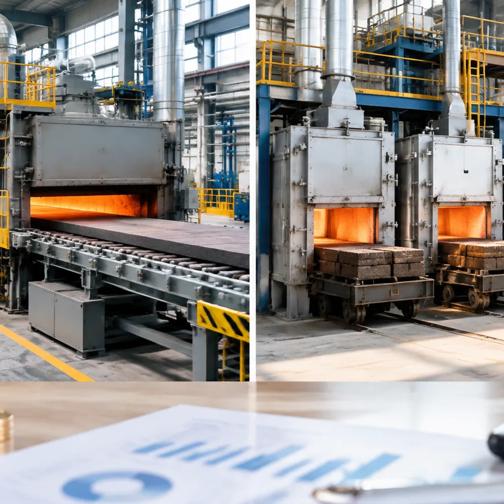
When we evaluate the economics of a continuous vs batch furnace battery project, we look straight at three drivers: installed capital, kilowatt-hours per kilogram of product, and first-pass yield. Thermal processing accounts for a massive share of cell manufacturing operating cost. Picking the wrong furnace setup turns into an ongoing financial bleed.
Equipment CAPEX, Plant Footprint, and Automation
Continuous roller hearth kilns demand heavy upfront capital. You are not just paying for a heated tunnel; you are buying closed-loop saggar handling automation, precision cross-transfer mechanisms, gas-tight lock chambers, and motorized return tracks.
-
- Continuous Kiln Layout: Requires a long, uninterrupted linear factory footprint (often 40 to 80 meters). The initial capital expense is high, but it scales well once throughput crosses gigawatt-hour levels.
- Batch Atmosphere Setup: Uses isolated box, pit, or car-bottom cells that fit into tighter, modular facility layouts. The initial machinery cost is roughly 60% to 75% lower. If you are assessing baseline budget allocations for controlled-atmosphere hardware, reviewing our vacuum furnace cost and price guide by capacity highlights how chamber sizing, sealing, and gas systems dictate capital costs.
Furnace Energy Efficiency Comparison and Thermal Inertia
In continuous processing, the furnace maintains a steady-state thermal equilibrium. Saggars enter, transfer heat, and exit while the refractory lining stays hot. In contrast, batch units cycle between ambient loading temperatures and process setpoints (often 750°C to 1,050°C for cathode material sintering).
-
- Refractory Thermal Inertia: In batch furnaces, thousands of kilograms of dense ceramic fiber and insulating firebrick absorb energy on every ramp-up, only to dump that heat during cooling. This wasted heat sharply increases production costs.
- Energy Consumption per Kilogram: Continuous roller hearth lines consume roughly 0.8 to 1.6 kWh/kg of finished active material. Batch operations draw anywhere from 2.5 to 5.0 kWh/kg for the exact same chemical formulation due to cyclical thermal losses.
Maintenance, Thermal Shock, and Component Life
Thermal cycling damages heating elements and fixtures. We see vastly different maintenance profiles across the two platforms:
-
- Heating Elements (SiC / MoSi2): Continuous furnaces keep elements under constant electrical load and uniform temperature, minimizing mechanical stress and oxidation. Batch furnaces subject elements to cyclical thermal expansion and contraction, accelerating micro-cracking and shortening service life.
- Saggar Longevity: Continuous kilns use staged cooling zones to protect cordierite-mullite saggars. Batch furnaces often push faster cooling cycles to turn over chambers, triggering thermal shock, warping, and premature saggar failure.
Labor Allocation and Material Scrap Rates
Automated roller hearth lines decouple labor from processing volume. A single operator station monitors loading, degassing, sintering, and return tracks. Batch operations require constant hands-on crane, forklift, and loading work to position saggars, purge chambers, and bolt down doors.
| Metric | Continuous Roller Hearth | Batch Atmosphere Furnace |
|---|---|---|
| Initial CAPEX | High ($$$$) | Low to Moderate ($$) |
| Specific Energy Consumption | 0.8 – 1.6 kWh/kg | 2.5 – 5.0 kWh/kg |
| Footprint Requirement | Long, linear continuous bay | Compact, modular footprint |
| Labor Demand | Low (Automated conveyor integration) | High (Manual/crane loading per run) |
| Thermal Shock to Consumables | Minimal (Steady-state heat zones) | High (Repeated ramp-and-soak cycles) |
| First-Pass Yield | High (>98% uniform batching) | Moderate (Edge effects cause scrap) |
Scrap rates tell the final story. In a batch car-bottom kiln, the saggars placed near the door and outer walls experience different heat absorption and gas velocities than those in the core. These edge-effect inconsistencies produce variations in crystal structure and incomplete de-binding, pushing scrap rates higher. Continuous kilns carry every single saggar through the exact same thermal curve and gas purge path, keeping first-pass yields high and repeatable.
Active Material Selection Matrix: Matching Furnace to Chemistry
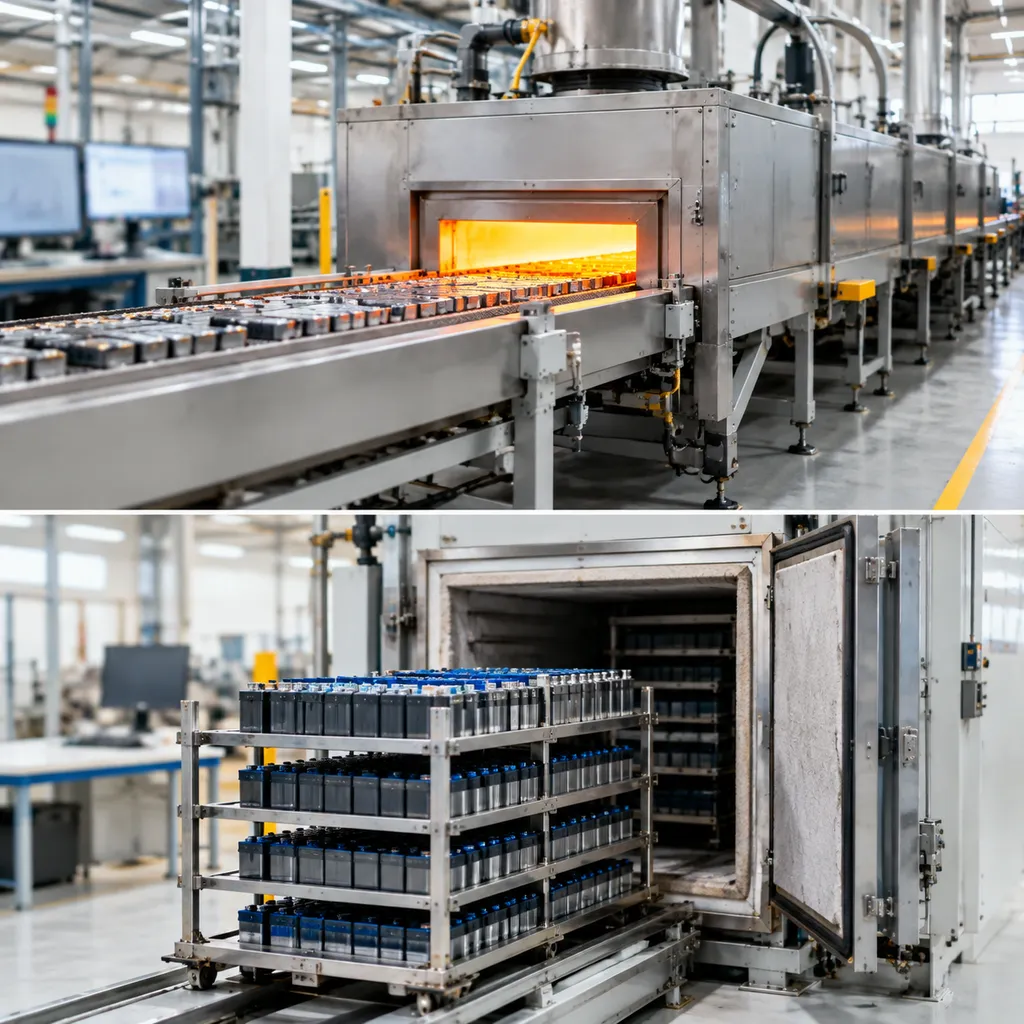
Choosing between a continuous vs batch furnace battery setup comes down to your chemical formulation, required atmospheric purity, and production volume. Different active chemistries demand completely different thermal profiles, gas exchange dynamics, and dwell times.
| Chemistry Type | Target Atmosphere | Typical Temp Range | Optimal Furnace Architecture | Critical Processing Hazard |
|---|---|---|---|---|
| NCM 811 / NCA | Ultra-pure Oxygen (O₂) | 750°C–850°C | Multi-atmosphere roller hearth | Lithium volatilization & corrosion |
| LFP / LMFP | Inert Nitrogen (N₂) | 650°C–800°C | High-volume continuous roller kiln | Incomplete carbon coating / oxidation |
| Synthetic Graphite / Si-C | Reducing / Inert (N₂ / Argon) | 900°C–1200°C | Pusher continuous or high-temp batch | Pitch outgassing & tar buildup |
| Solid-State Electrolytes | Controlled dry / vacuum | 800°C–1100°C | Sealed batch atmosphere furnace | Trace moisture contamination |
High-Nickel Ternary Cathodes (NCM 811, NCA)
For NCM high-nickel calcination, oxygen purity is non-negotiable. If oxygen levels dip below 95% to 99%, or if moisture exceeds single-digit parts per million, you risk cation mixing where Ni²⁺ ions displace Li⁺ in the crystal lattice. This drops your discharge capacity instantly.
-
The Furnace Match: We deploy continuous roller hearth systems built with gas-tight metallic muffles. Continuous flow prevents the thermal shock that causes severe saggar cracking, and automated multi-zone venting pulls off evaporated lithium salts before they condense onto heating elements.
-
Atmosphere Management: Counter-current O₂ sweep gas ensures fresh oxygen contacts the material during final crystal formation while flushing water vapor out through pre-heating exhaust ports.
Lithium Iron Phosphate (LFP / LMFP) High-Volume Synthesis
LFP synthesis furnace lines run on raw volume and tight carbon-coating dynamics. Any oxygen ingress above 20 ppm burns off the organic carbon source rather than pyrolyzing it into a conductive surface layer on the cathode particles.
-
The Furnace Match: High-throughput continuous roller kilns dominate this chemistry. Running hundreds of saggars per hour through steady nitrogen zones keeps production costs sustainable.
-
Purge Gas Economics: Running batch kilns for gigawatt-scale LFP wastes enormous volumes of purge gas due to repeated evacuation-and-fill cycles. A continuous tunnel maintains an established inert gas equilibrium, slashing continuous N₂ consumption per kilogram.
Anode Carbonization: Synthetic Graphite and Silicon-Carbon
Anode active material heating involves driving off volatile pitch binders at elevated temperatures up to 1200°C.
-
- Tar and hydrocarbon condensation present the biggest risk here; tar buildup inside exhaust ducting creates real fire hazards and clogs gas ports.
- For bulk synthetic graphite graphitization and pitch coating, continuous pusher slab furnaces or specialized roller hearths fitted with continuous tar-trapping condensors are the industry standard.
- For specialized silicon-carbon (Si-C) composites, we often utilize a sealed high-temperature sintering furnace during the chemical vapor deposition (CVD) or carbon-matrix baking step to manage reactive precursor gases precisely without contaminating larger manufacturing lines.
Solid-State Electrolytes and Experimental Chemistries
Solid-state battery components—such as LLZO (garnet-type) or sulfide-based electrolytes—require tight stoichiometric control and frequent recipe changes.
-
- Sulfide solid electrolytes are exceptionally sensitive to ambient air and release toxic H₂S gas on contact with trace moisture.
- Oxide-based solid electrolytes require prolonged sintering dwells at temperatures exceeding 1050°C to achieve full densification.
- The Furnace Match: A sealed batch atmosphere furnace provides the isolated environment necessary for these formulations. We rely on batch systems here because they allow full vacuum purge cycles, absolute dew-point verification below -60°C before heating, and zero risk of cross-contaminating commercial production lines.
Selection Framework: Choosing Continuous vs Batch Furnaces for Battery Facilities
Deciding between a continuous vs batch furnace battery layout comes down to matching your production volume, chemistry freeze status, and capital budget. We evaluate hundreds of thermal processing layouts every year, and picking the wrong thermal route either burns working capital in underutilized automation or bottlenecks output with soaring manual labor.
| Decision Driver | Batch Atmosphere Furnace | Continuous Roller Hearth Kiln |
|---|---|---|
| Target Scale | Pilot to < 2,000 tons/year | > 5,000 tons/year (Gigafactory scale) |
| Recipe Agility | High (fast profile swaps) | Low (locked thermal profile) |
| CAPEX / Initial Footprint | Lower initial cost, compact footprint | High equipment cost, large linear footprint |
| OPEX per Kilogram | Higher labor & gas purge costs | Optimized energy efficiency & low labor |
| Yield Consistency | Batch-to-batch variation risk | Highly uniform steady-state sintering |
When to Invest in Continuous Roller Hearth Kilns for Gigawatt-Scale Production
For commercial cathode material sintering at utility or EV scale, a roller hearth continuous furnace is the industry standard. Once your chemistry formula is locked and production exceeds roughly 300 to 500 kg/h, continuous systems deliver distinct operational advantages:
-
- Lowest Thermal Processing OPEX: Roller hearth kilns hold thermal equilibrium continuously, avoiding the cyclic heating and cooling of refractory brick that degrades batch furnace energy efficiency.
- Tight Gas Utilization: Continuous counter-flow designs sweep purge gases (high-purity O2 or N2) across counter-moving saggars, lowering gas consumption per kilogram of active material.
- Inline Automation: Continuous conveyance eliminates crane and forklift loading, feeding automated saggar dumping, washing, and powder refilling loops seamlessly.
When Advanced Batch Atmosphere Furnaces Make Sense for Flexible Processing
Committing to high-throughput continuous kilns too early creates financial drag if your chemistry changes every month. We specify advanced batch atmosphere furnaces for plants navigating distinct production constraints:
-
- Frequent Chemistry Swaps: If you bounce between synthetic graphite, silicon-carbon anodes, and multiple cathode grades, batch units let you switch atmospheres and thermal profiles between runs without downtime.
- Pilot Lines & Qualification Lots: Automotive qualification requires traceable, discrete batch records. Batch kilns isolate individual batches, ensuring an out-of-spec run doesn't contaminate thousands of kilograms of inline powder.
- Capital Conservation: When launching early commercial runs below 1,500 metric tons per year, batch units minimize initial plant footprint and keep upfront CAPEX manageable.
The Hybrid Model: Transitioning Formulations from Pilot Batch to Continuous Production
Most battery facilities run a phased hybrid model rather than an abrupt transition. We help plants validate core sintering kinetics in batch kilns before scaling into a high-capacity continuous sintering furnace platform:
-
- Kinetics Mapping: Pin down exact solid-state dwell times, de-binding zones, and off-gas purge rates inside bench-scale and car-bottom batch chambers.
- Profile Duplication: Translate multi-step batch soak curves into physical thermal zones inside a continuous roller kiln, matching travel speed to required residence times.
- Redundancy Retention: Keep small-footprint batch furnaces operational alongside high-volume continuous lines to process off-spec scrap re-runs, customer sampling runs, and next-generation precursor testing without breaking main line production.
Custom Thermal Engineering with Haitem Furnace
When choosing between a continuous vs batch furnace battery configuration, off-the-shelf equipment rarely meets exact material needs. We engineer our thermal platforms around your specific synthesis chemistry, volatile loads, and plant footprint requirements.
Every battery precursor reacts differently. Whether you run pilot runs in sealed chambers or high-volume cathode calcination on a moving hearth, we build the furnace envelope to match your target stoichiometry. Through our dedicated design and engineering services, we develop thermal hardware that eliminates cold spots, controls toxic off-gases, and stops atmosphere contamination before it ruins a batch.
Precision Gas-Tight Sealing and Multi-Zone Architecture
Atmosphere integrity decides cathode quality. If ambient moisture or carbon dioxide leaks into an NCM calcination chamber, residual lithium values spike and product yield drops instantly.
-
- Dual-Curtain Mechanical Seals: Nitrogen gas locks and mechanical labyrinth seals maintain positive pressure, preventing oxygen dilution during LFP sintering and maintaining O2 purity above 99.5% for high-nickel cathodes.
- Segmented Atmosphere Isolation: Exhaust baffles keep volatile off-gases—like lithium hydroxide vapor, carbon monoxide, and moisture—from bleeding back into high-temperature crystal growth zones.
- Independent Multi-Zone Temperature Regulation: We configure multi-zone atmosphere control across pre-heating, soaking, and cooling sections. Each zone uses individual PID loops and silicon carbide (SiC) or molybdenum disilicide (MoSi2) heating elements to keep temperature gradients within ±2°C.
Automated Saggar Handling and Thermal Optimization
Saggar movement creates the highest risk of particulate contamination and thermal shock. We build fully synchronized conveyance setups that link directly to your upstream dosing lines. Our custom process integration connects raw material feeding, kiln transport, and post-sintering cooling into a unified handling system.
| Automation Feature | Operational Function | Direct Process Benefit |
|---|---|---|
| Robotic Saggar Depalletizing | Precise servo-driven pick-and-place indexing | Prevents mechanical shock and eliminates saggar edge chipping |
| Dynamic Closed-Loop Conveyance | Variable-speed roller hearth continuous furnace drives | Allows real-time dwell-time shifts for custom crystal growth curves |
| Inline Profile Monitoring | Embedded multi-point thermocouple telemetry | Maps live temperature uniformity surveys across every saggar layer |
| Automated Return Loops | Continuous overhead or under-hearth saggar return | Minimizes heat loss during saggar turnaround and cuts overall energy use |
Matched to Proprietary Active Material Recipes
No two battery formulas share identical reaction kinetics. We tune the kiln's internal physical geometry, purge volume, and heat curve specifically for your active material recipe:
-
- High-Nickel Cathodes (NCM 811 / NCA): Built with pure nickel or high-alumina internal linings to prevent metal ion cross-contamination under hot, pressurized oxygen.
- LFP / LMFP Synthesis: High-velocity inert nitrogen flow systems that quickly purge organic binders without trapping carbon residues on particle surfaces.
- Silicon-Carbon & Synthetic Graphite Anodes: High-temperature sealed muffle designs rated for rigorous de-binding and carbonization profiles with integrated volatile condensing traps.
- Solid-State Electrolytes: Ultra-dry atmosphere batch chambers equipped with dew-point suppression systems rated down to -60°C.
Frequently Asked Questions: Continuous vs Batch Battery Furnaces
What is the break-even production volume to switch from batch to continuous furnaces?
In active material synthesis, the financial pivot point between a batch setup and a continuous roller hearth furnace typically sits between 300 and 500 metric tons per year (roughly equivalent to 0.5 to 1 GWh of cell production).
Below 300 tons annually, batch furnaces win on low capital expenditure, low idling costs, and formulation agility. Once production scales beyond this threshold, continuous kilns justify their higher initial investment through:
Drastically reduced manual labor via automated saggar return tracks
Lower baseline energy consumption per kilogram of processed material
Superior lot-to-lot electrochemical consistency across large-format battery cells
Can a batch atmosphere furnace achieve the purity required for NCM 811 calcination?
Yes, provided it is a sealed, high-integrity system. A properly engineered controlled atmosphere furnace can achieve the clean environment needed for high-nickel cathode sintering (O2 concentration > 99.5%, dew point below -40°C, and residual CO2 < 50 ppm).
To match the purity levels of a continuous roller hearth kiln, a batch system relies on:
Pre-firing vacuum evacuation: Eliminating trapped ambient air before the heating cycle begins.
Aggressive high-volume O2 sweeping: Removing off-gassed moisture and carbon dioxide released during lithium hydroxide decomposition.
Corrosion-resistant heating elements: Preventing heavy metal spallation that can poison sensitive cathode surfaces.
While batch processing achieves the target chemistry for pilot validation, gas consumption per kilogram is notably higher than the counter-current gas flow used in continuous kilns.
How does energy consumption per kilogram compare between roller hearth and box kilns?
The furnace energy efficiency comparison between these two designs comes down to thermal cycling versus steady-state operation:
| Furnace Configuration | Typical Energy Consumption | Primary Thermal Mechanism |
|---|---|---|
| Roller Hearth Continuous Kiln | 1.2 – 2.0 kWh/kg | Refractory hot zones stay at steady-state temperatures; energy is expended primarily on heating the saggars and active materials. |
| Batch / Industrial Box Kiln | 3.5 – 6.0 kWh/kg | The entire mass of insulation, heating elements, and chamber walls must be repeatedly heated and cooled with every cycle. |
For small R&D batches, a high-temperature box furnace offers the operational flexibility needed for rapid trial iterations. At production scale, however, the continuous furnace uses significantly less power per kilogram because it avoids continuous thermal cycling of the furnace lining.
What maintenance practices prevent cross-contamination and saggar thermal shock?
Maintaining product purity and extending saggar life across continuous vs batch furnace battery operations requires structured handling protocols:
-
- Control heating and cooling gradients: Limit thermal ramps to 3–5°C/min. Exceeding recommended cooling rates induces severe mechanical stress in cordierite-mullite or high-alumina saggars, causing micro-cracking and spalling.
- Implement automated dry-cleaning stations: Utilize high-pressure filtered air knives and rotary ceramic brushes paired with negative-pressure HEPA extraction to clean saggars between cycles. Liquid washing should be avoided to prevent residual moisture from boiling during calcination.
- Dedicated chemistry loops: Segregate saggar inventory strictly by chemistry. Never run lithium iron phosphate (LFP) in saggars previously exposed to nickel-rich or cobalt-containing formulations.
- Periodic visual and acoustic crack testing: Inspect saggars before refilling to catch thermal fatigue cracks early, preventing saggar collapse inside continuous hot zones.